Engine Exhaust Systems with Secondary Air Injection Systems

Active Publication Date: 2007-10-18
KOHLER CO
View PDF62 Cites 45 Cited by
  • Summary
  • Abstract
  • Description
  • Claims
  • Application Information

AI Technical Summary

Benefits of technology

[0015] Further, in at least some embodiments, the present invention relates to a method of reducing a component of exhaust emissions from an internal combustion engine. The method includes providing air to a valve, and communicating the air past the valve when the valve is open. The metho

Problems solved by technology

Nevertheless, conventional catalytic converter technology has several disadvantages that make it not highly desirable, for use in many applications such as the above-mentioned small off-road engines.
In particular, catalytic converters tend to be fairly complicated and expensive due to their use of precious metal catalysts.
Further, catalytic converters tend to lack durability and tend to deter

Method used


Image

  • Engine Exhaust Systems with Secondary Air Injection Systems
  • Engine Exhaust Systems with Secondary Air Injection Systems
  • Engine Exhaust Systems with Secondary Air Injection Systems

Examples


first embodiment

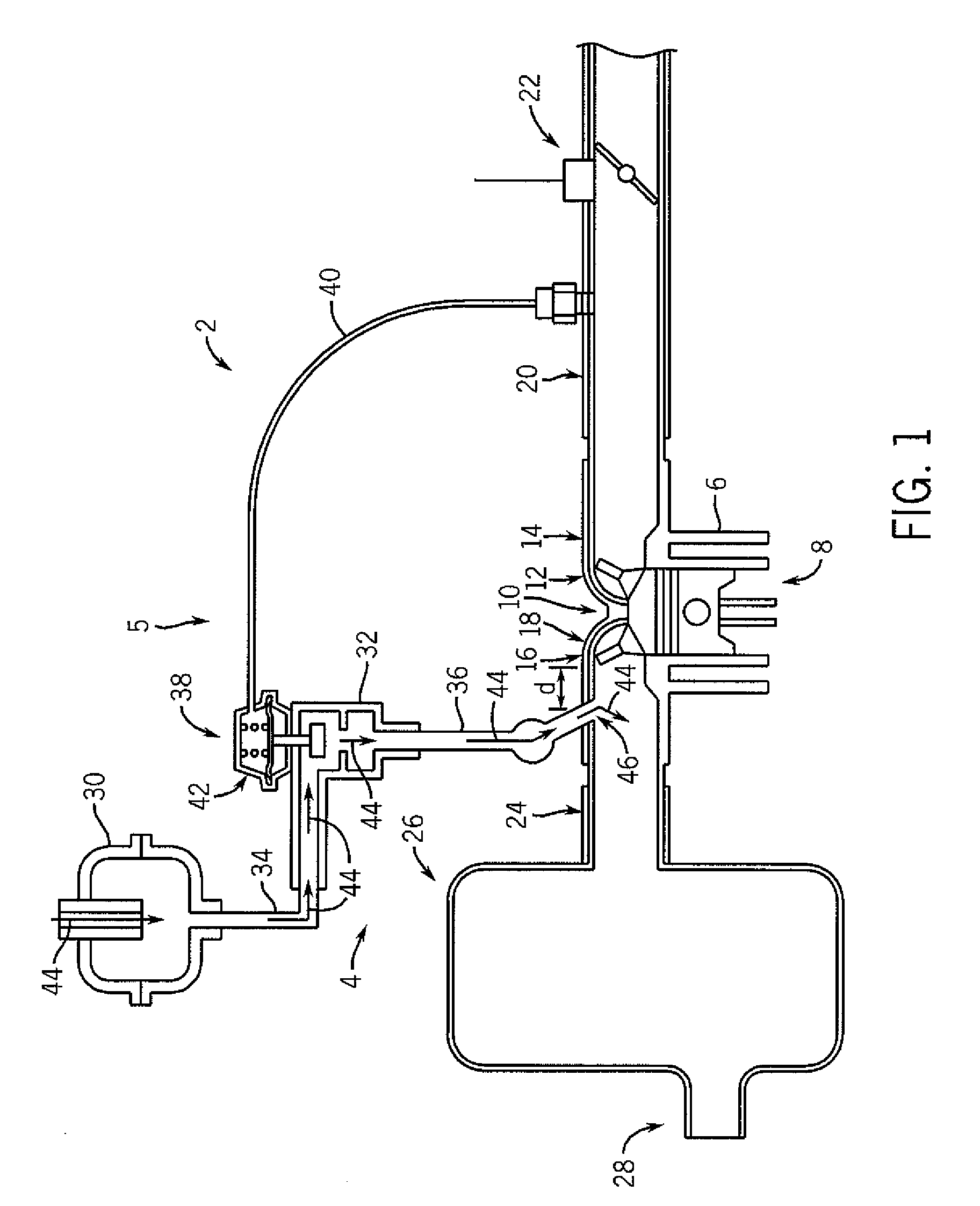
[0034] In at least some additional embodiments, the present invention applies to engines that have less than one liter in displacement, or engines that both have less than one liter in displacement and fit within the guidelines specified by the above-mentioned regulations. In still further embodiments, the present invention is intended to encompass other small engines, large spark ignition (LSI) engines, and / or other larger (mid-size or even large) engines. 341 Referring to FIG. 1, a portion of a first engine 2 having an exhaust system 4 is shown in schematic form. As shown, the engine 2 includes a cylinder 6 within which reciprocates a piston 8. Also included within the engine 2 is a cylinder head 10 that includes both an intake port 12 within which can open and close an intake valve 14 and an exhaust port 16 within which can open and close an exhaust valve 18. The intake port 12 is coupled to an intake conduit or manifold 20, along which is positioned a throttle 22 that governs a ...

second embodiment

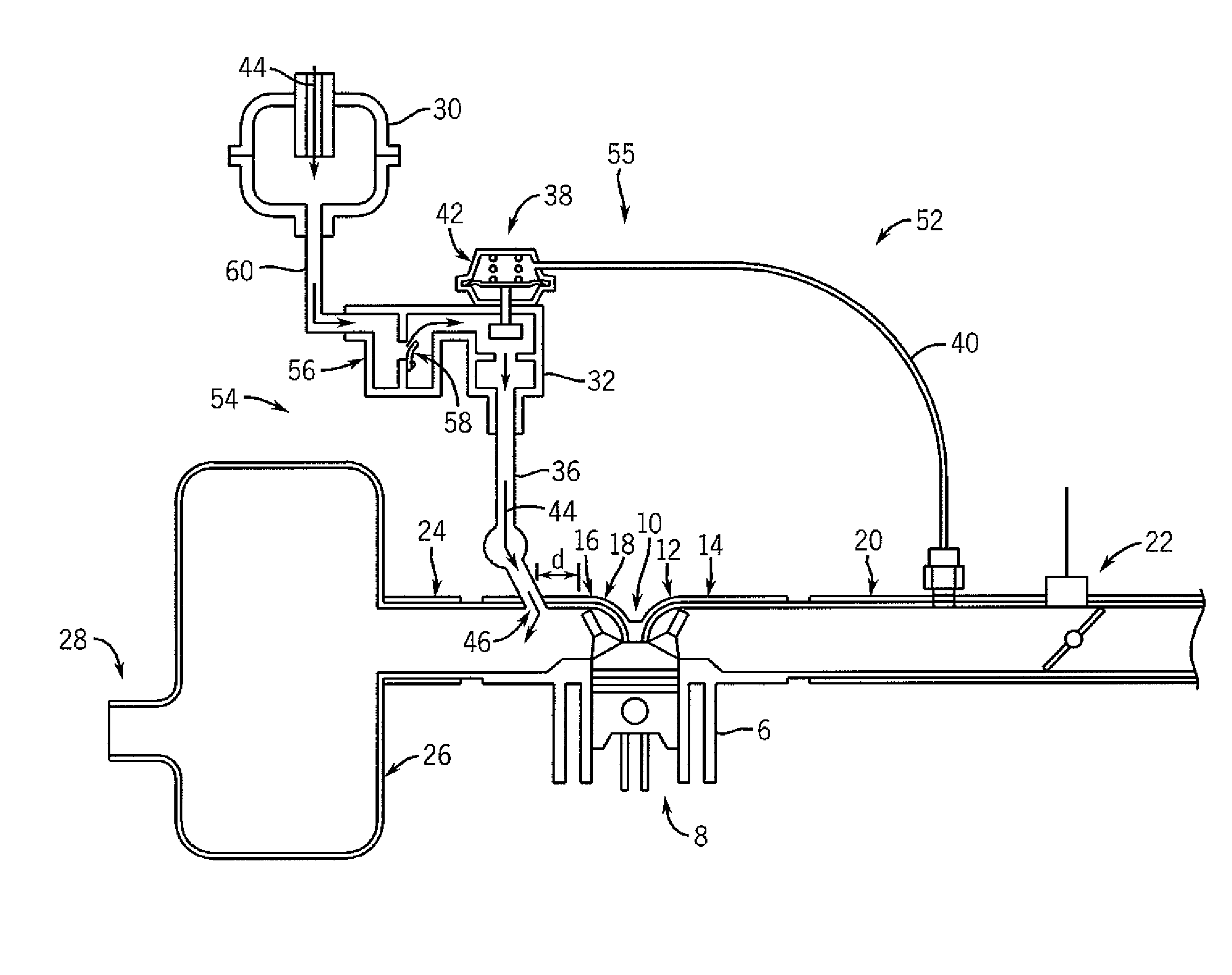
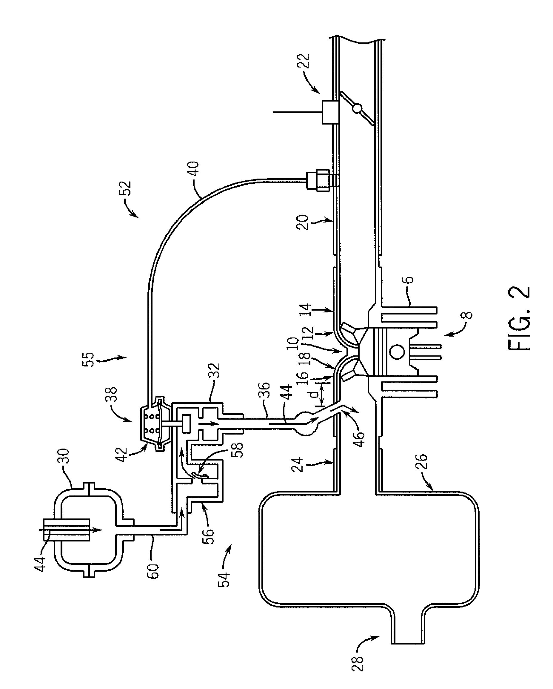
[0042] Turning to FIG. 2, a portion of a second engine 52 having an exhaust system 54 is shown. As with the engine 2 of FIG. 1, the engine 52 includes the cylinder 6, piston 8, cylinder head 10, intake port 12, intake valve 14, exhaust port 16, exhaust valve 18, intake manifold 20, throttle 22, exhaust manifold 24, muffler 26, and exhaust outlet 28. The exhaust system 54 of the engine 52 in particular also is a SAI thermal reactor exhaust system having a SAI system 55 that, like the SAI system 5, includes the resonator 30, the control valve assembly 32 with valve actuator 38 and vacuum chamber 42, the vacuum line 40, and the second secondary air conduit 36 with orifice 46 being positioned at a distance d from the exhaust port 16. In contrast to the SAI system 5 of FIG. 1, however, the SAI system 55 includes not only the control valve assembly 32, but also includes a second, one-way valve assembly 56 including a one-way valve member 58 that allows air flow to occur in only one direct...

third embodiment

[0050] Referring to FIG. 3, a portion of a third engine 62 having an exhaust system 64 is shown. The engine 62 again includes the cylinder 6, piston 8, cylinder head 10, intake port 12, intake valve 14, exhaust port 16, exhaust valve 18, intake manifold 20, throttle 22, thermal reactor muffler 26, and exhaust outlet 28. The exhaust system 64, like the exhaust system 54 in FIG. 2, is a SAI exhaust system having a SAI system 65 that includes each of the resonator 30 that receives air from an air supply, the first secondary air conduit 60, the one-way valve assembly 56 with the valve member 58, the control valve assembly 32 with valve actuator 38 and vacuum chamber 42, and the vacuum line 40. In contrast to the engine 52 of FIG. 2, however, the exhaust port 16 is coupled to the muffler 26 by way of a modified exhaust manifold 74 having first and second orifices 76 and 78, respectively, and the control valve assembly 32 is coupled to these two orifices by way of a Y-shaped secondary air...


PUM


Abstract

A variety of embodiments of exhaust systems for engines including small off-road engines, and related methods of operation, are disclosed. In at least some embodiments, the exhaust system includes a first conduit that receives exhaust emissions from a first engine cylinder, and a second conduit that communicates air to a first port on the first conduit. The air mixes with the exhaust emissions within the first conduit so as to produce a chemical reaction, and a level of at least one undesirable component of the exhaust emissions is reduced. Further, the exhaust system does not include any catalytic converter. In some embodiments, the exhaust system further comprises a crankcase ventilation system.

Description

CROSS-REFERENCE TO RELATED APPLICATIONS [0001] This application claims priority to the co-pending U.S. Provisional Patent Application No. 60 / 792,993, filed Apr. 18, 2006, incorporated herein by reference.FIELD OF THE INVENTION [0002] The present invention relates to internal combustion engines and, more particularly, to exhaust systems in internal combustion engines. BACKGROUND OF THE INVENTION [0003] Internal combustion engines are used in a wide variety of applications. As a result of the internal combustion process, such engines necessarily generate exhaust emissions having a variety of carbon-based and other substances. Increasingly it desired that internal combustion engines be capable of operating in a manner such that at least one or more components of these exhaust emissions from the engines are reduced or eliminated. [0004] Further, legislation has recently been (or is in the process of being) enacted in various jurisdictions such as California placing restrictions on the e...

Claims


Application Information

Patent Timeline
IPC IPC(8): F01N3/00
CPCF01N3/34F01N3/227Y02T10/20F01N3/22F01N3/10Y02T10/12
Inventor PEKRUL, ERICHUDAK, ERIC
Owner KOHLER CO
Why Eureka
Try Eureka