
Air purifier

Inactive Publication Date: 2007-10-18
L2B ENVIRONMENTAL SYST
View PDF12 Cites 15 Cited by
  • Summary
  • Abstract
  • Description
  • Claims
  • Application Information

AI Technical Summary

Benefits of technology

[0008] In accordance with another aspect of this invention, there is provided an air purifier comprising an air flow cavity bounded by cavity walls; a source of ultraviolet light for emitting ultraviolet light such that ultraviolet light is present within said cavity; an ultraviolet light reflective coating on said cavity walls; and a plurality of photocatalytic particles associated with said reflective coating, said photocatalytic particles of a type which leads to production of oxygen and hydroxyl free radicals when illuminated with ultraviolet light in the presence of water wherein said photocatalytic particles cover 0.01% to 5.0% of a surface area of said reflective coating so as to not materially affect UV reflectance.

Problems solved by technology

One drawback with this approach is that biological material may not be exposed to UV light for a sufficient time to be sterilized.
In operation, a fan draws air through the filter resulting in biological material becoming trapped in the filter.
However some biological material, namely viruses, readily pass through porous filters and would not, therefore, be sterilized with the combination of a porous filter in conjunction with a UV lamp.
Furthermore, UV light degrades a porous filter requiring frequent replacement of same.
While this embodiment results in an effective purifier, water misters may not be readily available and increase maintenance needs of a system.

Method used


Image

  • Air purifier
  • Air purifier
  • Air purifier

Examples


Embodiment Construction

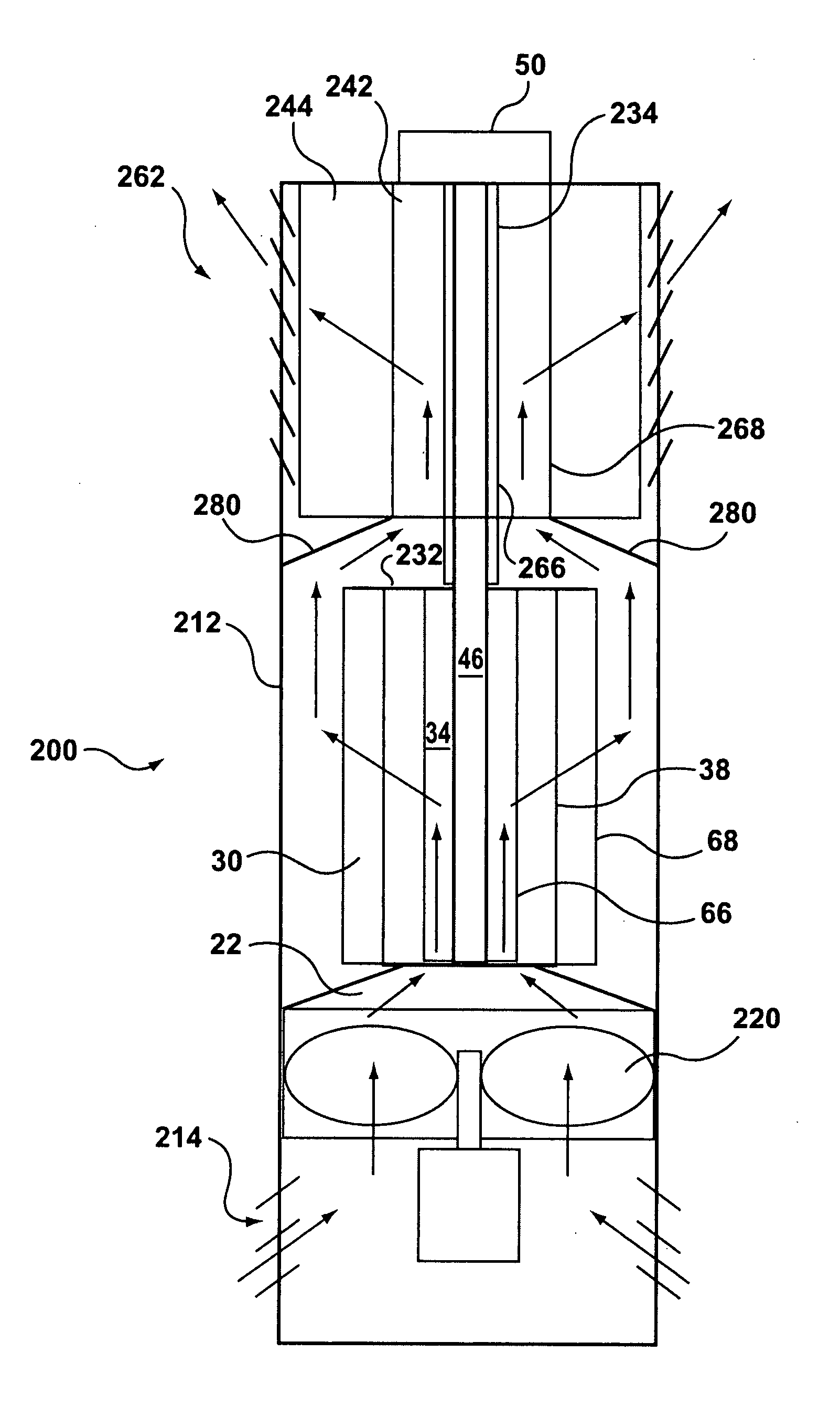
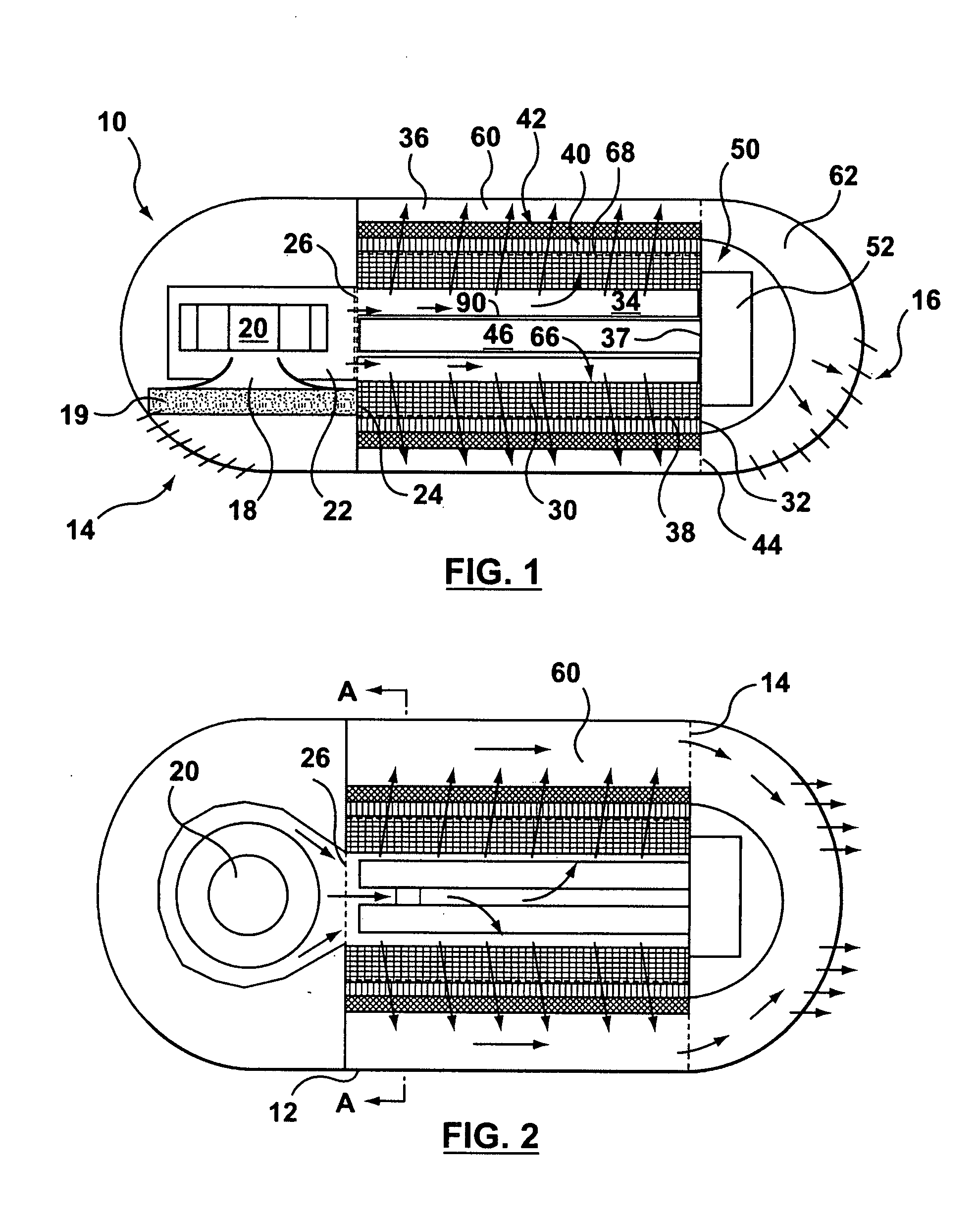
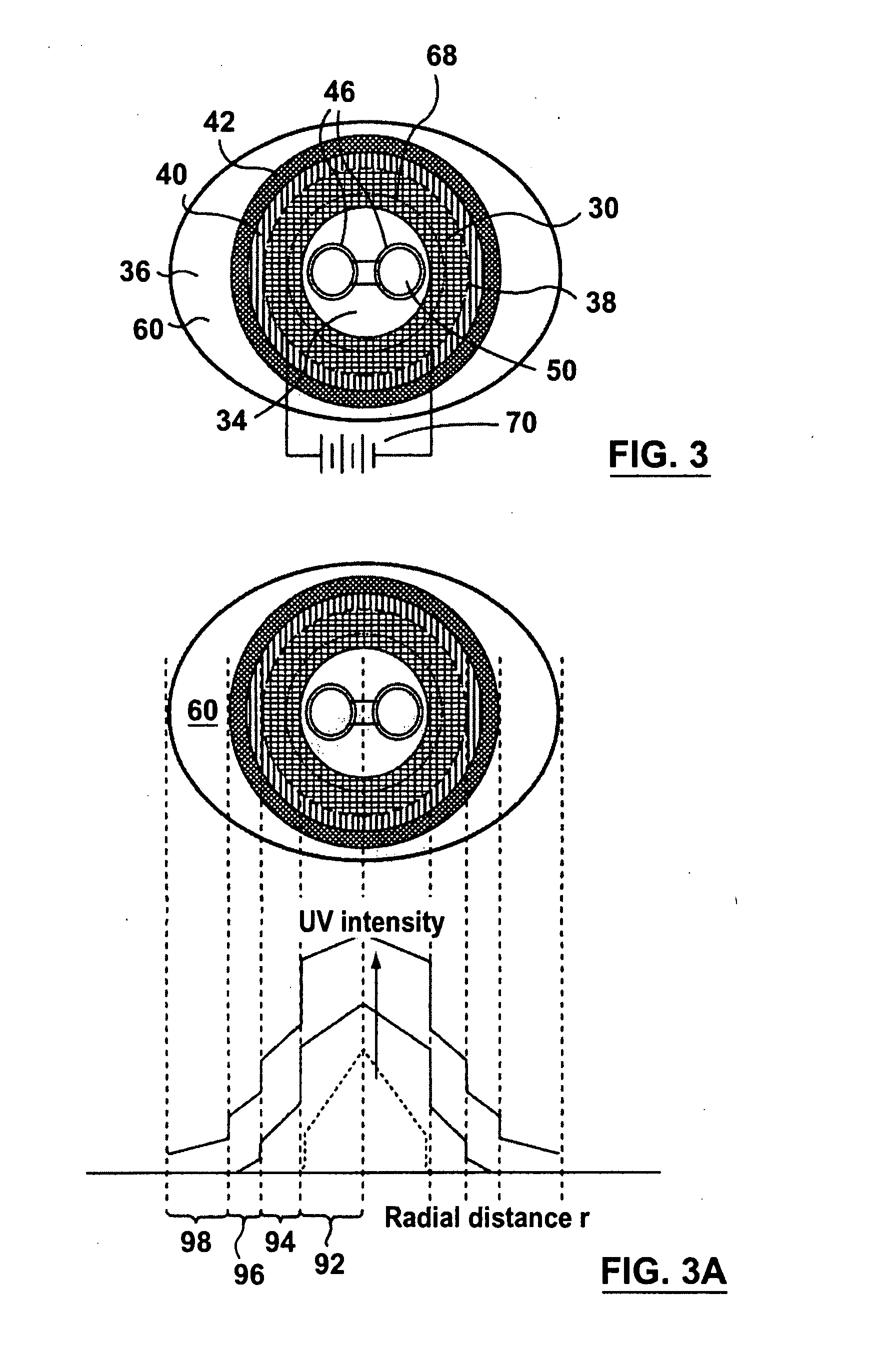
[0018] Referencing FIGS. 1 to 3, an air purifier 10 has a housing 12 with an air intake 14 and an air exhaust 16. Within housing 12, an intake plenum 18 extends from the air intake 14, through a dust filter 19, to the suction inlet of a blower 20. An outlet plenum 22 extends between the outlet of the blower and an annular wall 24 inwardly depending from housing 12. Annular wall 24 has a concentric aperture covered with an ultra-violet (“UV”) reflecting screen mesh 26 which allows the flow of air but which reflects UV. An annular dielectric body 30 extends between annular wall 24 and a second annular wall 32 inwardly depending from the housing to define a central cavity 34 and a peripheral annular cavity 36. Dielectric body 30 is enveloped by a screen mesh sleeve 38, a particulate filter 40, and a chemically absorbent filter 42. Sleeve 38 may, optionally, be provided with a UV coating on its inside surface such that it allows the transmission of air but reflects UV. The second annula...


PUM

PropertyMeasurementUnit
Fractionaaaaaaaaaa
Fractionaaaaaaaaaa
Fractionaaaaaaaaaa

Abstract

An air purifier has an air flow cavity bounded by cavity walls and a source of ultraviolet light emitting ultraviolet light within the cavity. The cavity walls have an ultraviolet light reflective coating. A plurality of photocatalytic particles are associated with the reflective coating. The photocatalytic particles are of a type which leads to production of oxygen and hydroxyl free radicals when illuminated with ultraviolet light in the presence of water.

Description

CROSS-REFERENCE TO RELATED APPLICATIONS [0001] This application is a continuation of U.S. application Ser. No. 09 / 961,632 filed Sep. 24, 2001, the contents of which are incorporated herein by reference.BACKGROUND OF THE INVENTION [0002] This invention relates to an air purifier and to a method of air purification. [0003] It is known that ultraviolet (“UV”) light sterilizes DNA so that biological material (such as viruses, bacteria, molds, yeasts, and pollens) exposed to UV light either dies or cannot reproduce. This property of UV light has been utilized to sterilize air in a building by simply placing UV lamps in the building's air ducts. One drawback with this approach is that biological material may not be exposed to UV light for a sufficient time to be sterilized. To address this drawback, it is known to utilize a porous air filter and mount a UV light for reciprocating movement across a face of the filter. In operation, a fan draws air through the filter resulting in biological...

Claims


Application Information

Patent Timeline
IPC IPC(8): A62B31/00C09D1/00C09D17/00
CPCC09D1/00C09D17/008Y10T428/25Y10T428/263Y10T428/26
Inventor MORROW, WILLIAM H.MCLEAN, LARRY JAMES
Owner L2B ENVIRONMENTAL SYST
Learn More