Orientation insensitive thermosiphon of v-configuration

a technology of orientation and temperature, applied in the direction of lighting and heating apparatus, instruments, semiconductor/solid-state device details, etc., can solve the problem of relatively low air heat capacity and achieve the effect of lowering the cost of manufacturing

Inactive Publication Date: 2007-10-25
DELPHI TECH INC
View PDF21 Cites 46 Cited by
  • Summary
  • Abstract
  • Description
  • Claims
  • Application Information

AI Technical Summary

Benefits of technology

[0012] The invention provides an alternative design for a compact heat exchanger for cooling an electronic device able to operate in a vertical position, a horizontal position or

Problems solved by technology

Heat exchangers and heat sink assemblies have been used that apply natural or forced convection cooling methods to dissipate heat from electroni

Method used


Image

  • Orientation insensitive thermosiphon of v-configuration
  • Orientation insensitive thermosiphon of v-configuration
  • Orientation insensitive thermosiphon of v-configuration

Examples


Embodiment Construction

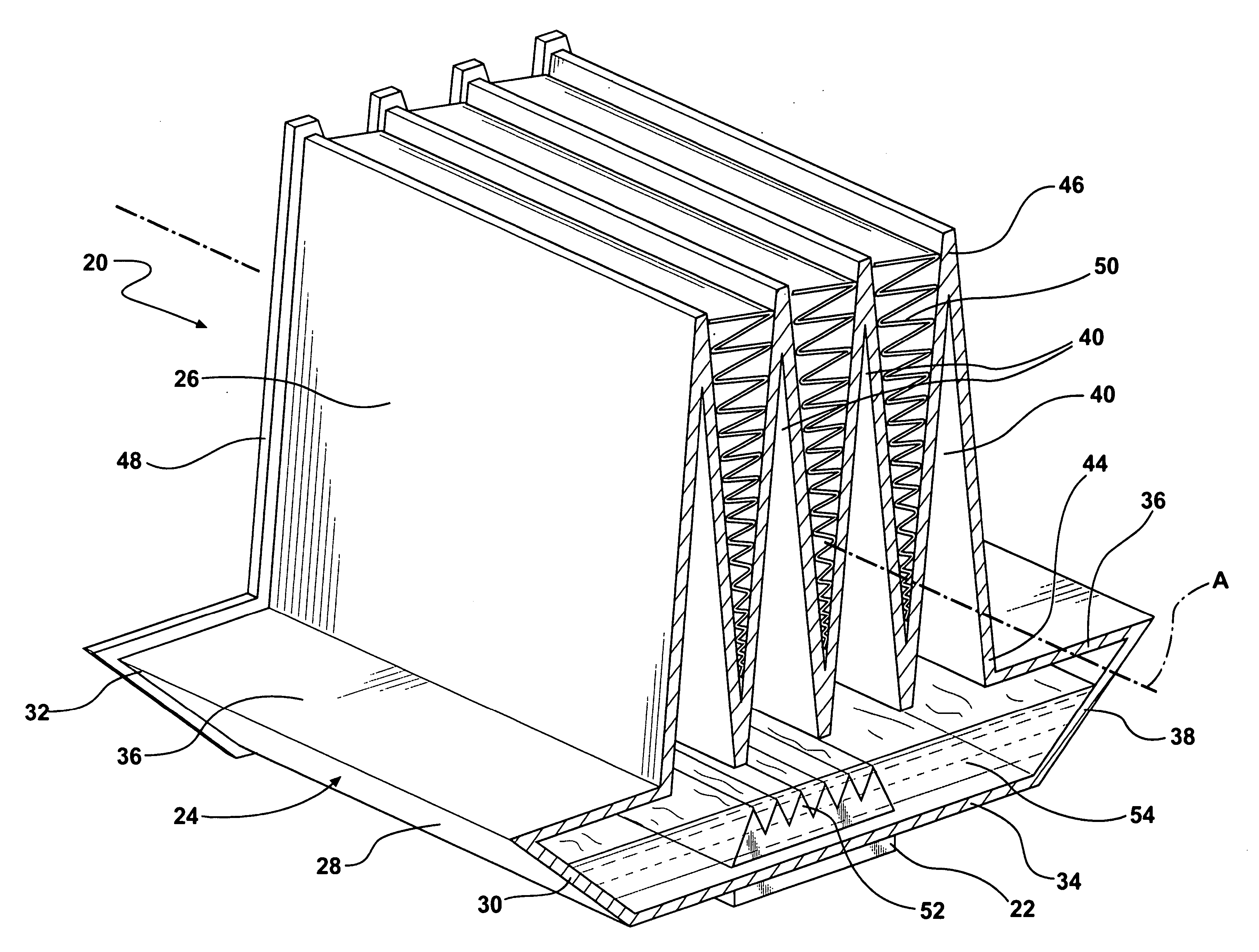
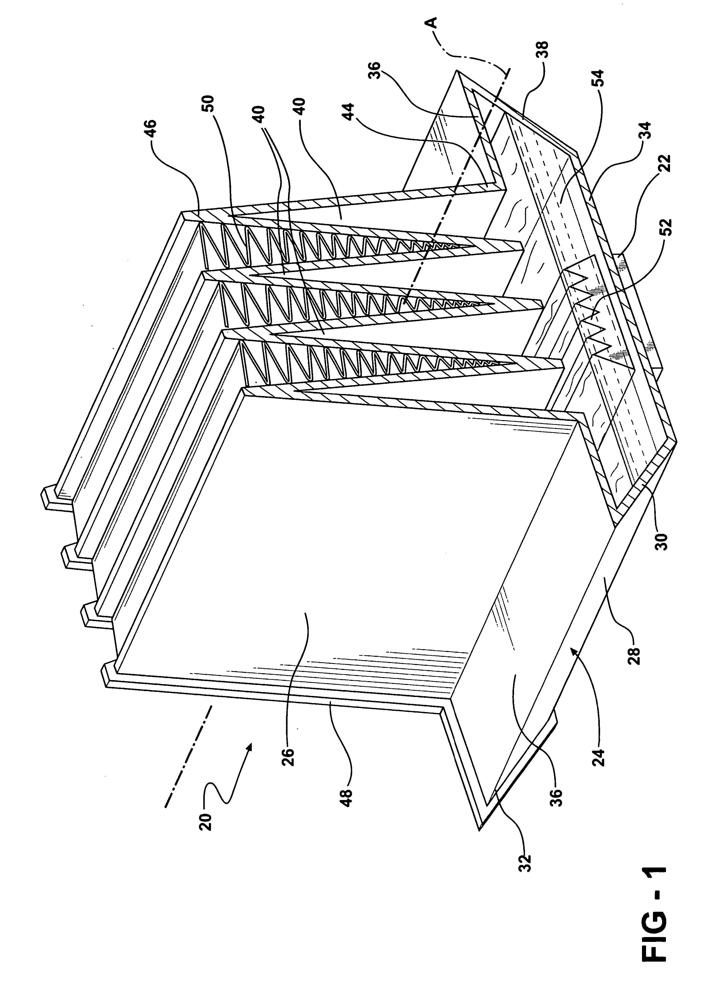
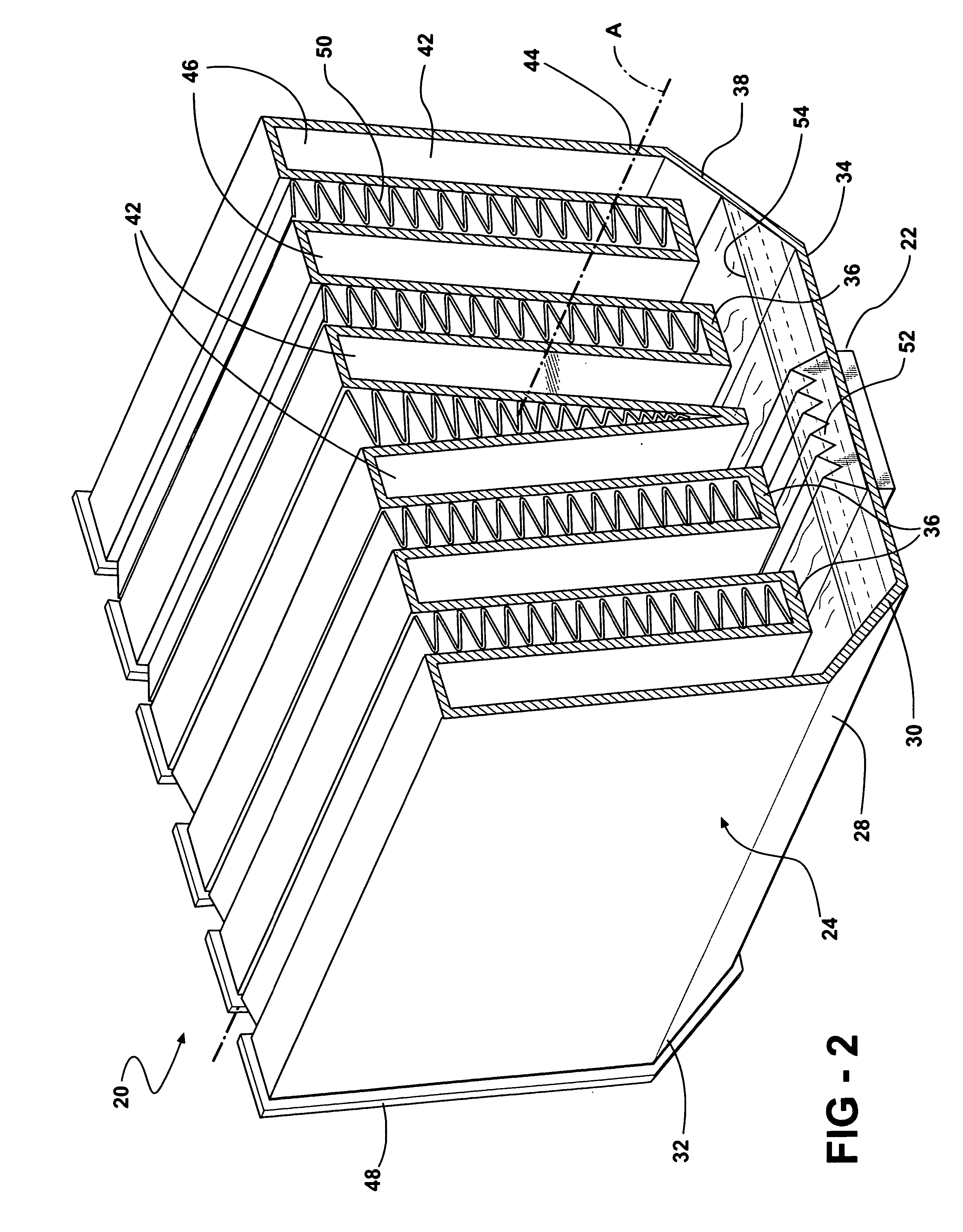
[0016] Referring to the Figures, wherein like numerals indicate corresponding parts throughout the several views, a heat exchanger assembly 20 is generally shown for cooling an electronic device 22.

[0017] The assembly 20 includes a housing 24 generally indicated having an upper portion 26 and a lower portion 28 extending along a primary axis A, and having a front end 30 and a back end 32. The lower portion 28 of the housing 24 includes a floor 34, a top wall 36, and diverging side walls 38 extending outwardly and upwardly from the floor 34 to the top wall 36. The upper portion 26 of the housing 24 includes a plurality of condensing tubes 40, 42 extending axially and spaced from one another transversely to the axis. Each condensing tube extends upwardly from a bottom end 44 at the lower portion 28 of the housing 24 to distal and spaced top ends 46.

[0018] In the embodiment shown in FIG. 1, the top wall 36 extends from the side walls 38 horizontally and inwardly to the upper portion ...


PUM


Abstract

The invention provides a heat exchanger assembly for cooling an electronic device wherein the upper portion of the housing includes a plurality of condensing tubes extending upwardly from the lower portion of the housing. A plurality of air heat transfer fins zigzag transversely to a primary axis (A) between adjacent ones of the condensing tubes for dissipating heat from vapor boiled off of the refrigerant. At least two next adjacent condensing tubes of the plurality diverge upwardly from the bottom ends toward the top distal ends thereof. Accordingly, the space containing the air heat transfer fins between the two next adjacent condensing tubes is greater at the top distal ends than at the bottom ends of the condensing tubes. The condensing tubes can either have a constant cross-section with diverging tube axes or can have a decreasing cross-section from bottom to top with parallel tube axes.

Description

BACKGROUND OF THE INVENTION [0001] 1. Field of the Invention [0002] The subject invention relates to a heat exchanger assembly for cooling an electronic device. [0003] 2. Description of the Prior Art [0004] The operating speed of computers is constantly being improved to create faster computers. With this, comes an increase in heat generation and a need to effectively dissipate that heat. [0005] Heat exchangers and heat sink assemblies have been used that apply natural or forced convection cooling methods to dissipate heat from electronic devices that are highly concentrated heat sources such as microprocessors and computer chips; however, air has a relatively low heat capacity. Thus, liquid-cooled units called LCUs employing a cold plate in conjunction with high heat capacity fluids have been used to remove heat from these types of heat sources. Although LCUs are satisfactory for moderate heat flux, increasing computing speeds have required more effective heat sink assemblies. [000...

Claims


Application Information

Patent Timeline
IPC IPC(8): H05K7/20F28F19/00
CPCF28D15/0233F28F3/025G06F1/20H01L23/3672H01L23/427H01L2924/0002H01L23/467H01L2924/00
Inventor BHATTI, MOHINDER SINGHREYZIN, ILYAJOSHI, SHRIKANT MUKUNDPAWLAK, JOHN LAWRENCE III
Owner DELPHI TECH INC
Why Eureka
Try Eureka