Carrierless RFID system

a carrierless, impulsive technology, applied in the direction of electrical signalling details, mechanical actuation of burglar alarms, instruments, etc., can solve the problems of difficult to achieve long operational distance between transponder and reader in passive transponder, low circuit efficiency of tag thereby, and short range of passive transponder, etc., to achieve high efficiency and utilize the available power

Inactive Publication Date: 2007-10-25
MARTEC
View PDF7 Cites 24 Cited by
  • Summary
  • Abstract
  • Description
  • Claims
  • Application Information

AI Technical Summary

Benefits of technology

[0012] Accordingly, one object of the current invention is to provide a carrierless RFID system with high efficiency during tag energizing by utilizing the available power effectively by a rectifier.
[0014] A further object of the current invention is to provide a carrierless RFID system with high data rate for communication by using wideband spectrum allowing high data rate communication.
[0015] An even further object of the current invention is to provide a carrierless RFID system with high data security level by means of making interception and unintended detection quite difficult due to noise-like property of signals.
[0016] Still another object of the current invention is to provide a carrierless RFID system that is resistant to multipath and jamming and has very little interference with existing radio systems due to a large bandwidth allowing very high multipath resolution and huge frequency diversity.
[0017] An even further object of the current invention is to provide a carrierless RFID system that is relatively low complexity and low cost. The carrierless system according to this invention has essentially baseband nature of the signal transmission. Therefore there is no need for up-(down) conversion and amplification, a local oscillator and phase tracking loops.
[0018] Another object of the current invention is to provide a carrierless RFID system that possesses a high location and tracking performance. The carrierless system according to this invention allows very good timing precision due to large bandwidth.

Problems solved by technology

However, a disadvantage of passive transponders is a short range.
Thus, only a small proportion of incoming power is effective and circuit efficiency of the tag thereby is very low.
As a result, it is difficult to achieve long operational distance between transponder and reader in passive transponder.
As is evident from what is said above, there are serious draw backs in the currently known systems.

Method used


Image

  • Carrierless RFID system
  • Carrierless RFID system
  • Carrierless RFID system

Examples


Embodiment Construction

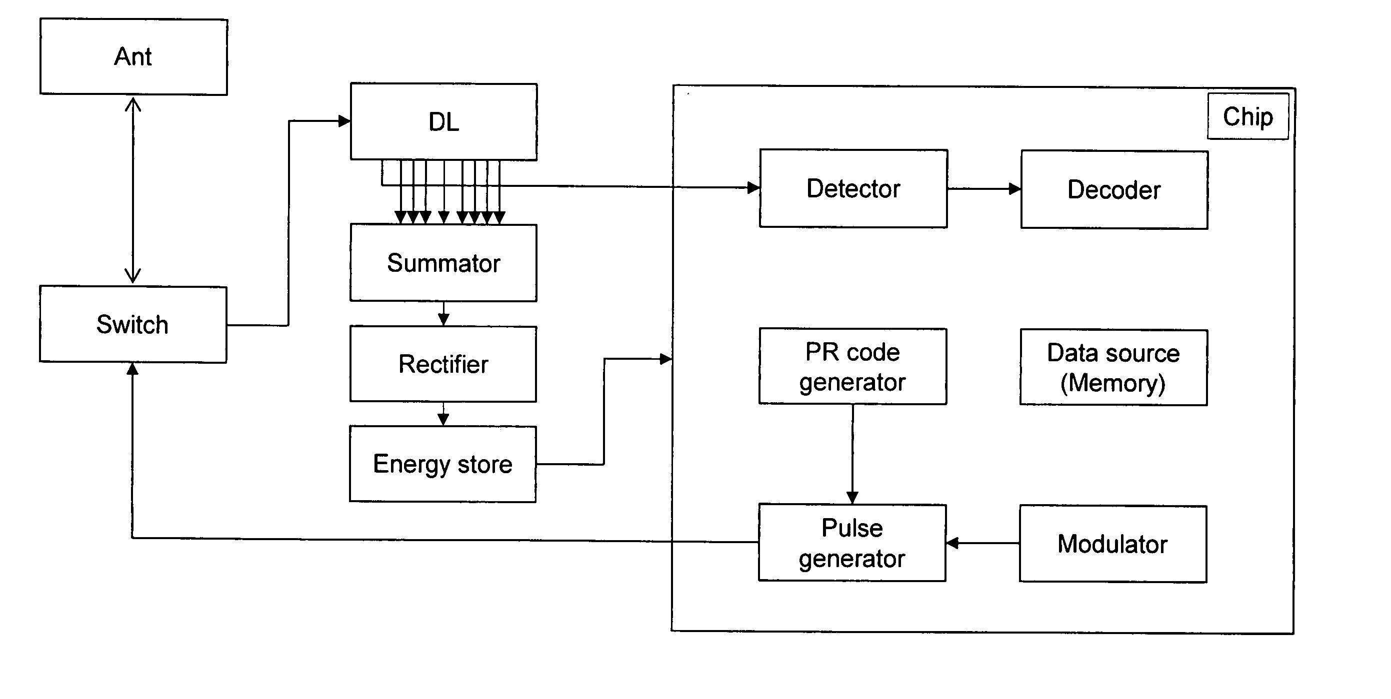
[0032] In this disclosure the term ‘carrierless’ is used to emphasize the difference to the general RFID systems which use a carrier to transfer power to a tag and to communicate. The term ‘carrierless RFID’ is used here as a synonym for ‘impulse RFID’ to emphasize the difference to general RFID systems which use a continuous wave signals as opposed to the impulse signals.

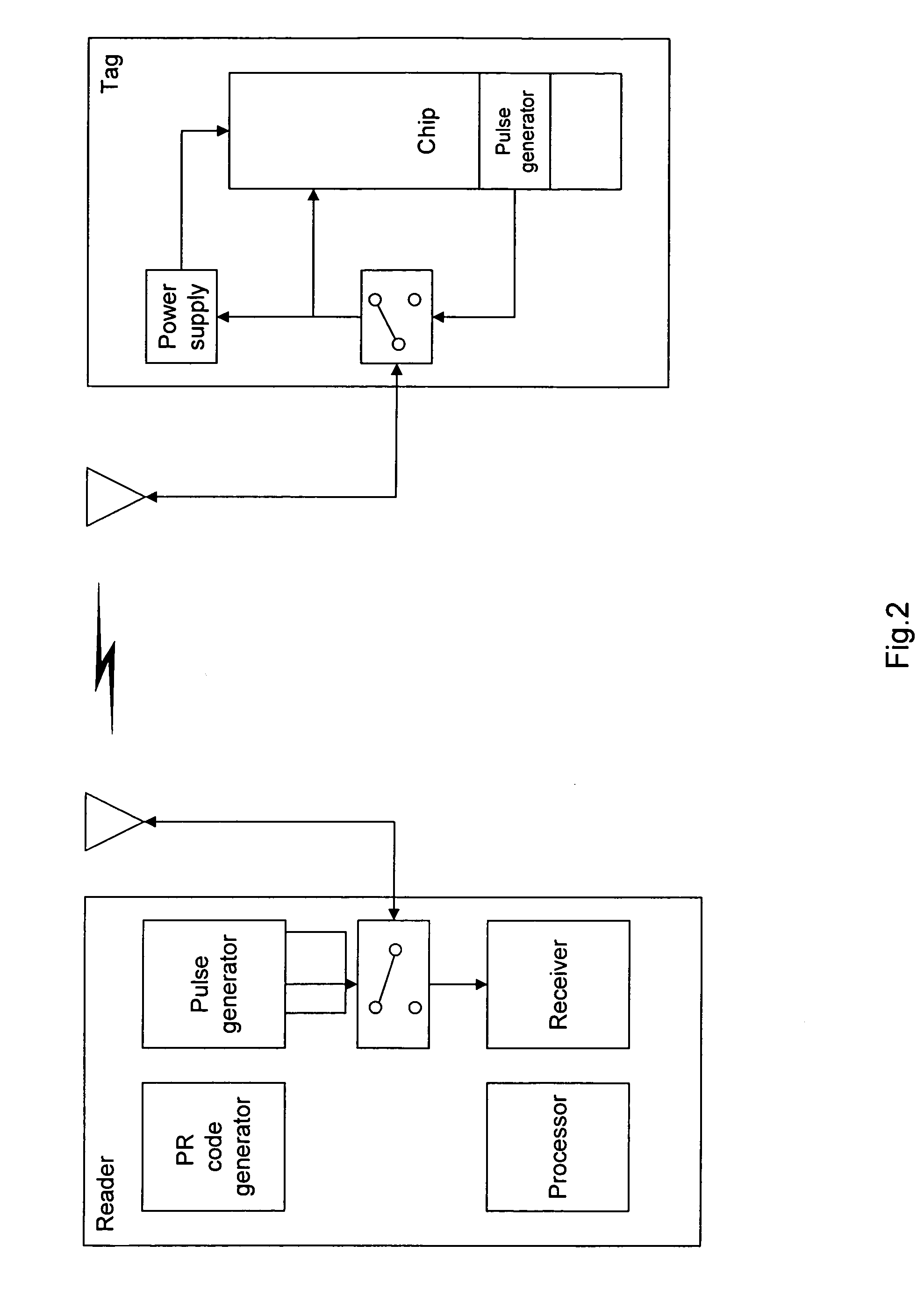
[0033] The present invention is a method and an apparatus to use carrierless (impulse) signals for energizing remote passive or active transponders (tags) and for a communication link between a reader and the transponders. The reader's transceiver generates very short high power pulses to transmit them to the transponder which receives and stores the pulse energy in an energy store on the transponder. At the transponder the power pulse signal is compressed by a matched filter and rectified. Information to be transmitted from the reader to the transponder and from the transponder to the reader can be added to the d...


PUM


Abstract

The present invention is a method and an apparatus to use carrierless signals for energizing remote passive or active transponders (tags) and for communication link between a reader and the transponders. The reader's transceiver generates very short high power pulses to transmit them to the transponder which receives and stores the pulse energy in an energy store on the transponder. At the transponder the power pulse signal is compressed by a matched filter and rectified. Information to be transmitted from the reader to the transponder and from the transponder to the reader can be added to the data pulses by means of pulse position modulation, bi-phase modulation or other well-known wide-band modulation techniques. The communication is active as the transponder utilizes stored power for transmission and reception of signals while the transponder can be passive and is powered by the reader's signal energy.

Description

TECHNICAL FIELD [0001] This invention is related to the field of radio frequency identification (RFID), and more particularly to methods for carrierless (impulse) RFID-systems. BACKGROUND [0002] RFID technology is one of many identification technologies in the automatic data identification industry. RFID market is growing sector of the radio technology industry, which brings together elements from many varied fields such as RF / microwave technology, semiconductor technology, telecommunications, data protection and cryptography, manufacturing technology, IT and many related areas. [0003] Generally speaking a RFID system consists of two components, namely the transponder or tag, which is located on the object to be identified and the interrogator or reader, which may be a read or read / write device. [0004] The heart of the RFID system lies in the transponder that carries information. The transponder responses to a coded RF signal received from the reader. Low cost and small size transpo...

Claims


Application Information

Patent Timeline
Patent Type & Authority Applications(United States)
IPC IPC(8): G08B13/14H04Q5/22
CPCG06K7/0008H04B1/7163G06K7/10306
Inventor MUCHKAEV, ARTEM
Owner MARTEC
Why Eureka
Try Eureka