Zoom optical system having liquid lens

a technology of optical system and liquid lens, applied in the field of zoom optical system, can solve the problems of increasing hindering the miniaturization of the camera module, and increasing the weight and power consumption, so as to reduce mechanical limitation, power consumption and weight

Inactive Publication Date: 2007-10-25
SAMSUNG ELECTRO MECHANICS CO LTD
View PDF1 Cites 30 Cited by
  • Summary
  • Abstract
  • Description
  • Claims
  • Application Information

AI Technical Summary

Benefits of technology

[0010]The present invention has been made to solve the foregoing problems of the prior art and therefore an aspect of the present invention is to provide a zoom optical system which moves only one lens group, thereby achieving miniaturization and reduces mechanical limitation, power consumption and weight.
[0012]Further another aspect of the invention is to provide a zoom optical system capable of achieving high resolution and superior aberrational characteristics and executing superior zooming function with use of a fewer number of lenses.
[0013]Yet another aspect of the invention is to provide a zoom optical system which is mountable in a product that requires ultra-miniaturization and high reliability withstanding drop impact.

Problems solved by technology

However, such functions require a driving means for driving the lenses, which in turn hinders miniaturization of the camera module.
This resultantly hinders miniaturization, increases weight and power consumption.

Method used


Image

  • Zoom optical system having liquid lens
  • Zoom optical system having liquid lens
  • Zoom optical system having liquid lens

Examples


example 1

[0092]The following Table 1 shows numeric data by Example 1 according to the present invention.

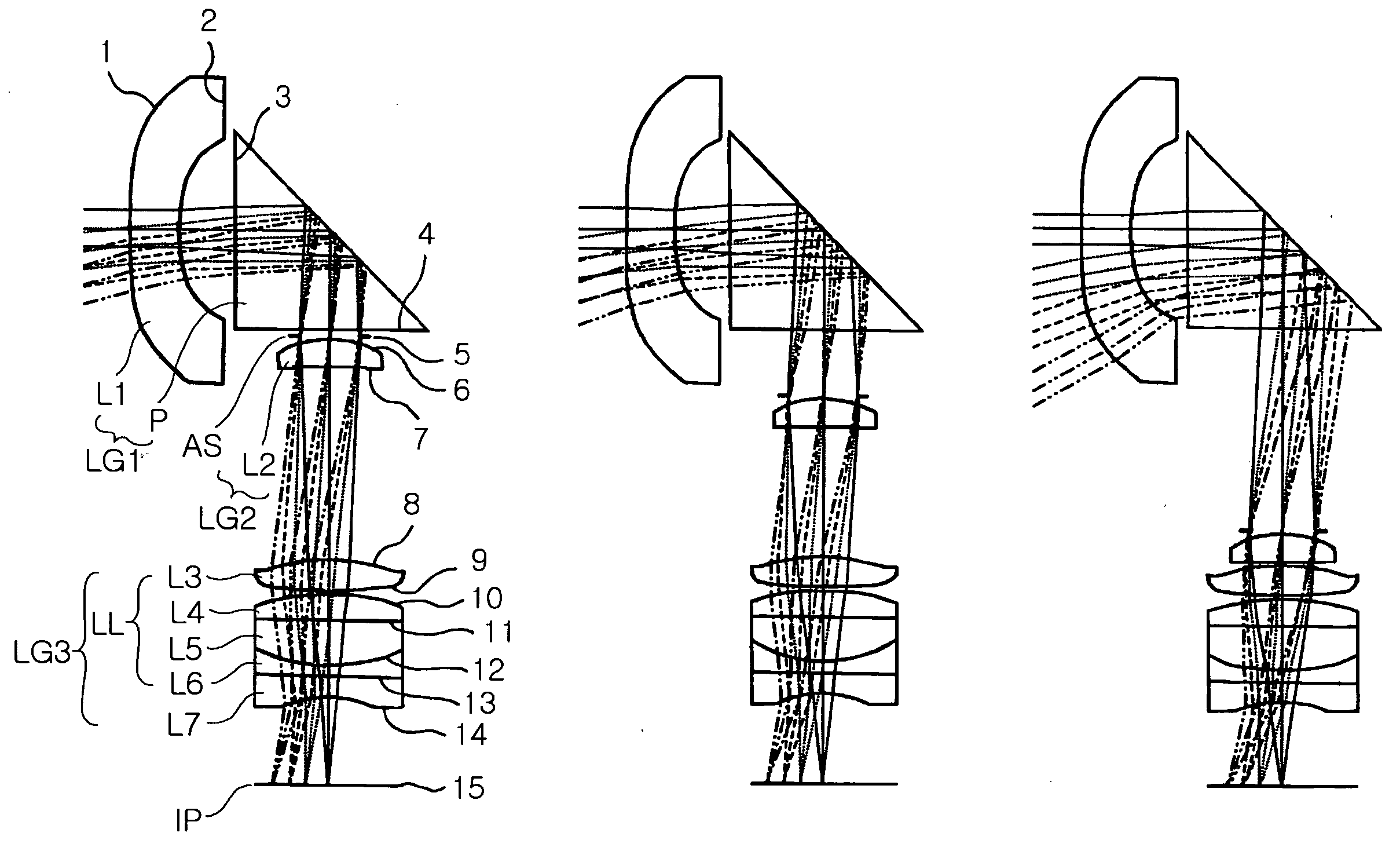
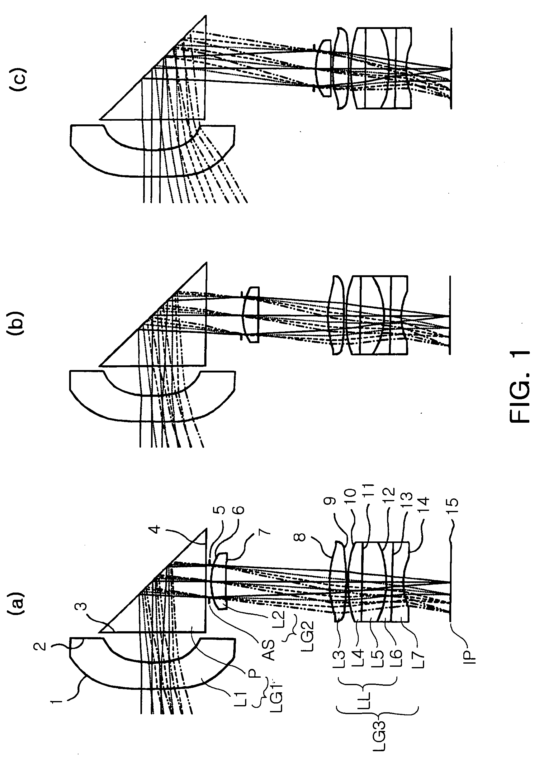
TABLE 1ThicknessAbbeSurfaceRadius oforRefractivenumberNo.curvature Rdistance tindex NdVdOther*1205.3481.3001.71247.6First lens*25.7291.5003∞5.2201.50956.4Prism4∞variable 15∞0.100Aperturestop*63.4930.7181.48770.4Second lens*742.159variable 2*85.5170.8001.48770.4Third lens*9−13.5640.100106.6790.6721.48770.4Fourth lens11∞variable 31.41633.5Fifth lens12variable 5variable 41.51722.3Sixth lens13∞0.5581.75527.6Seventh lens143.2602.31515∞—Image plane

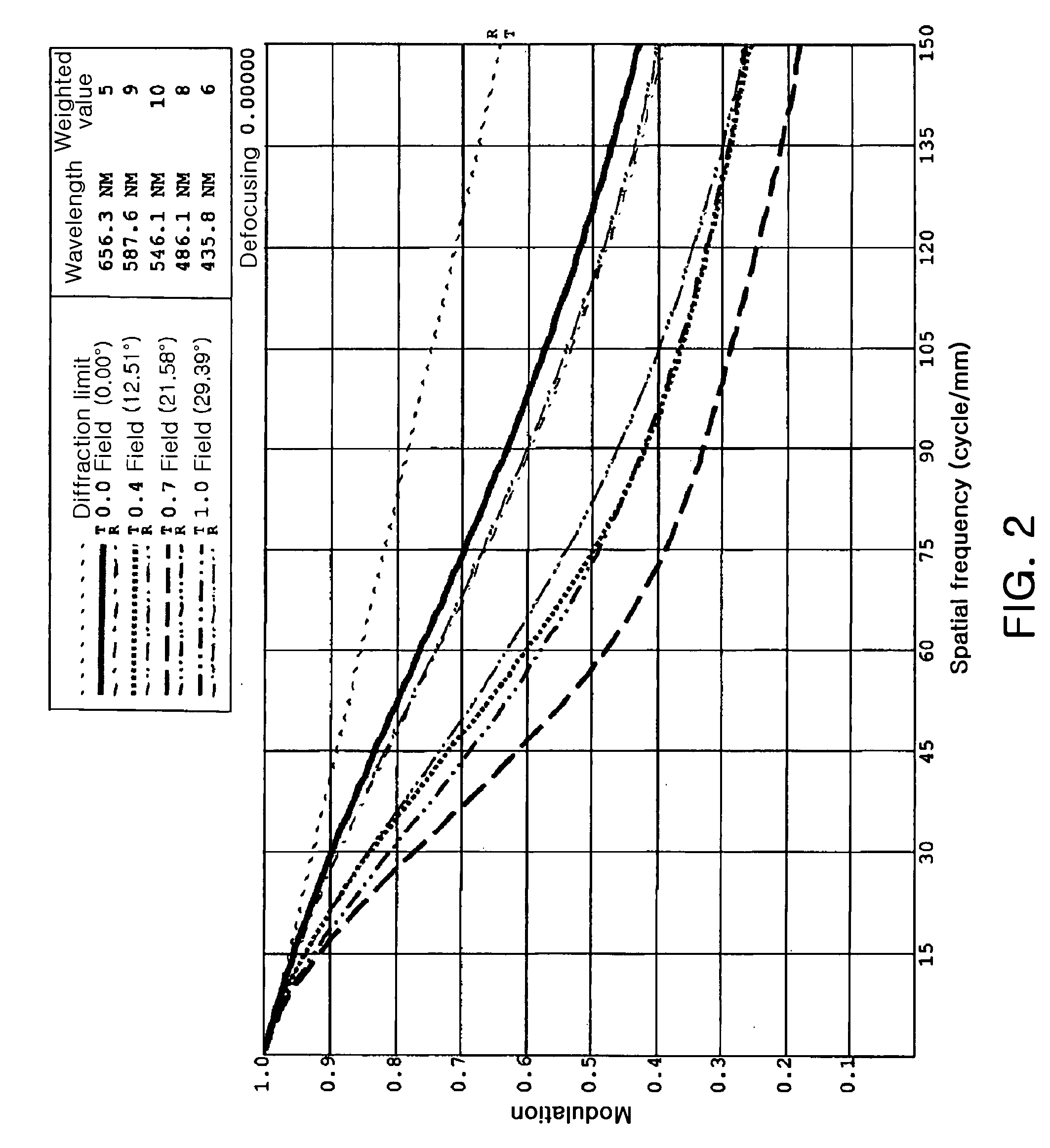
[0093]In addition, FIG. 1 is the lens arrangement of the zoom optical system according to Example 1 of the present invention, in which (a) is at a telephoto end, (b) is at a middle end and (c) is at a wide angle end. FIGS. 2 to 4 are graphs showing the Modulation Transfer Function (MTF) characteristics of the zoom optical system shown in FIG. 1 at a wide angle end, a middle end and a telephoto end, respectively, and FIGS. 5 to 7 are graphs showing...

example 2

[0101]The following Table 5 shows numeric data by Example 2 according to the present invention.

TABLE 5ThicknessAbbeSurfaceRadius oforRefractivenumberNo.curvature Rdistance tindex NdVdNote*120.0000.8261.74444.9First lens*25.1001.2593∞5.2201.50956.4Prism4∞variable 15∞0.100Aperturestop*62.0571.1351.48770.4Second lens*73.693variable 283.2980.9041.62060.3Third lens9∞variable 31.41633.5Fourth lens10variable 5variable 41.51722.3Fifth lens11∞0.4001.75527.6Sixth lens122.8420.300*132.1950.8501.62060.3Seventh lens*144.5561.56415∞—Image plane

[0102]In addition, FIG. 8 illustrates the lens arrangement of the zoom optical system according to Example 2, in which (a) is at a telephoto end, (b) is at a middle end and (c) is at a wide angle end. FIGS. 9 to 11 are graphs illustrating the MTF characteristics of the zoom optical system shown in FIG. 8 at a wide angle end, a middle end and a telephoto end, respectively. FIGS. 12 to 14 are graphs illustrating spherical aberration, astigmatism and dist...

example 3

[0107]Table 9 shows numeric data by Example 3 according to the present invention.

TABLE 9ThicknessAbbeSurfaceRadius oforRefractivenumberNo.curvature Rdistance tindex NdVdNote*120.0000.8981.50660.8First lens*25.1001.5003−15.0005.2201.50956.4Prism414.692variable 15∞0.100Aperturestop*61.7351.4001.48770.4Second lens*73.667variable 283.1740.8821.48770.4Third lens9∞variable 31.41633.5Fourth lens10variable 5variable 41.51722.3Fifth lens11∞0.4001.75527.6Sixth lens122.6660.631*132.3980.8501.62060.3Seventh lens*144.4751.16215∞—Image plane

[0108]In addition, FIG. 15 is the lens arrangement of the zoom optical system by Example 3 according to the present invention, in which (a) is at a telephoto end, (b) is at a middle end and (c) is at a wide angle end. FIGS. 16 to 18 are graphs illustrating the MTF characteristics of the zoom optical system shown in FIG. 15 at a wide angle end, middle end, telephoto end. FIGS. 19 to 21 are graphs illustrating aspherical aberration, astigmatism and distorti...


PUM


Abstract

A zoom optical system mountable in an ultra-small camera module. A first lens group is disposed stationary and has a negative refractive power. The first lens group includes at least one lens and a prism for converting the paths of light incident through the lens. A second lens group is disposed movable to execute zooming and has a positive refractive power. A third lens group is disposed stationary and has a positive refractive power. The third lens group includes a liquid lens having a meniscus formed between non-miscible first and second liquids, the first liquid having conductivity and polarity. The meniscus is changed in its radius of curvature in response to voltage application and functions as a refracting surface, by which the third lens group corrects an image plane in accordance with zooming by the second lens group. This allows optimal zooming capacity with high resolution and superior aberrational characteristics.

Description

CLAIM OF PRIORITY[0001]This application claims the benefit of Korean Patent Application No. 2006-35606 filed on Apr. 20, 2006, in the Korean Intellectual Property Office, the disclosure of which is incorporated herein by reference.BACKGROUND OF THE INVENTION[0002]1. Field of the Invention[0003]The present invention relates to a zoom optical system for a camera module using an image sensor such as a Charge Coupled Device (CCD) and a Complementary Metal-Oxide-Semiconductor (CMOS) and, more particularly, to a zoom optical system which drives a fewer number of lens groups with use of a liquid lens and is small-sized with a simple mechanical structure, capable of achieving high resolution.[0004]2. Description of the Related Art[0005]In general, a camera has a plurality of lenses and adjusts the relative distances thereof to thereby execute optical zoom, automatic focus and close-up functions.[0006]Recently, mobile communication terminals or Personal Digital Assistants (PDAs) with a camer...

Claims


Application Information

Patent Timeline
Patent Type & Authority Applications(United States)
IPC IPC(8): G02B15/14
CPCG02B3/14G02B15/177G02B5/04G02B15/143507G02B3/0087G02B7/04G02B13/009
Inventor KIM, TAE YOUNG
Owner SAMSUNG ELECTRO MECHANICS CO LTD
Why Eureka
Try Eureka