

Three degree of freedom parallel mechanism, multi-axis control machine tool using the mechanism and control method for the mechanism
a technology of multi-axis control and parallel mechanism, which is applied in the direction of mechanical control devices, process and machine control, instruments, etc., can solve the problems of jointing rod deformation, inability to compensate, and errors in positioning, so as to improve the responsiveness of control, improve the accuracy of positioning control, and improve the effect of operation speed and speed
- Summary
- Abstract
- Description
- Claims
- Application Information
AI Technical Summary
Benefits of technology
Problems solved by technology
Method used
Image

Examples
first embodiment
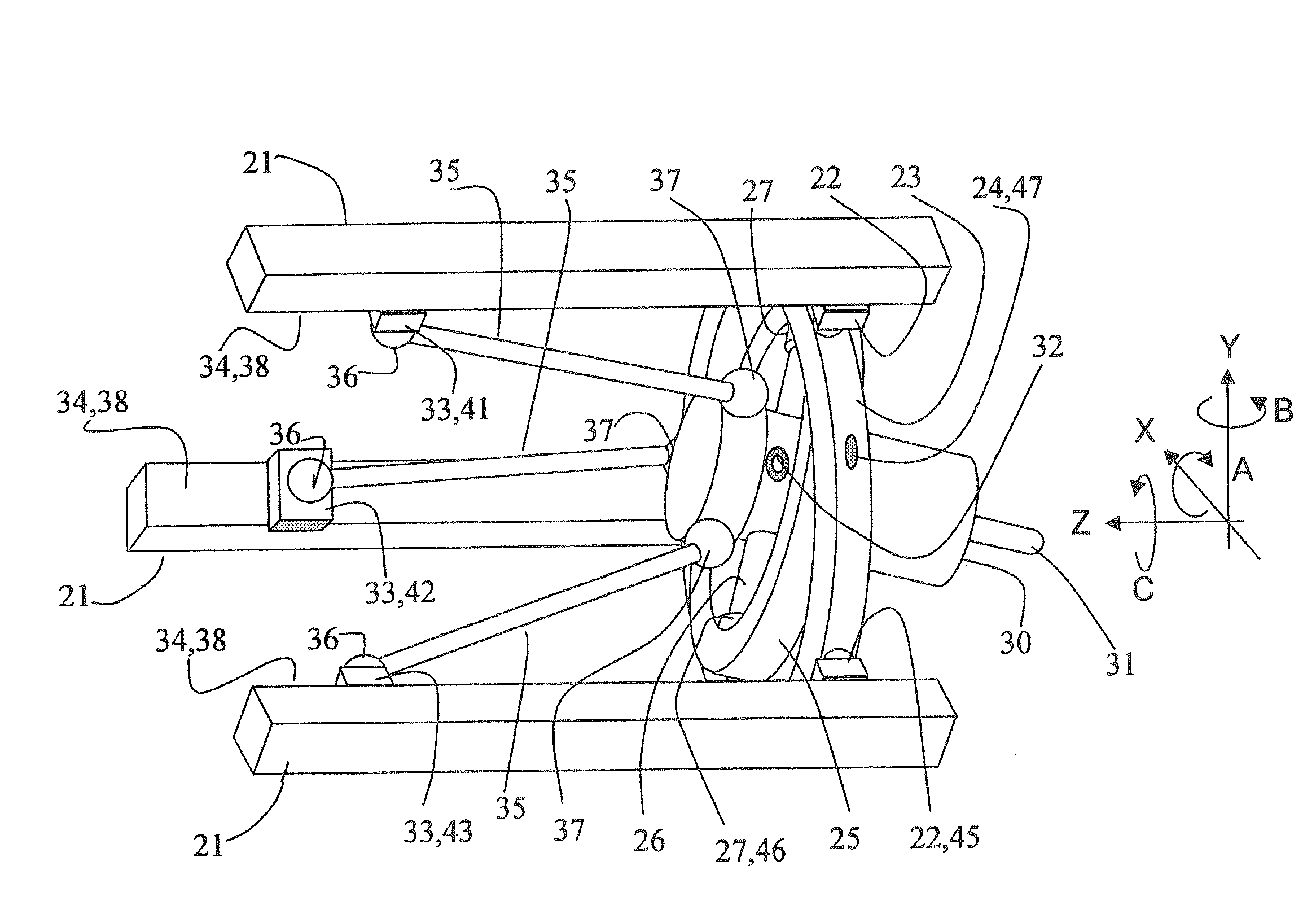
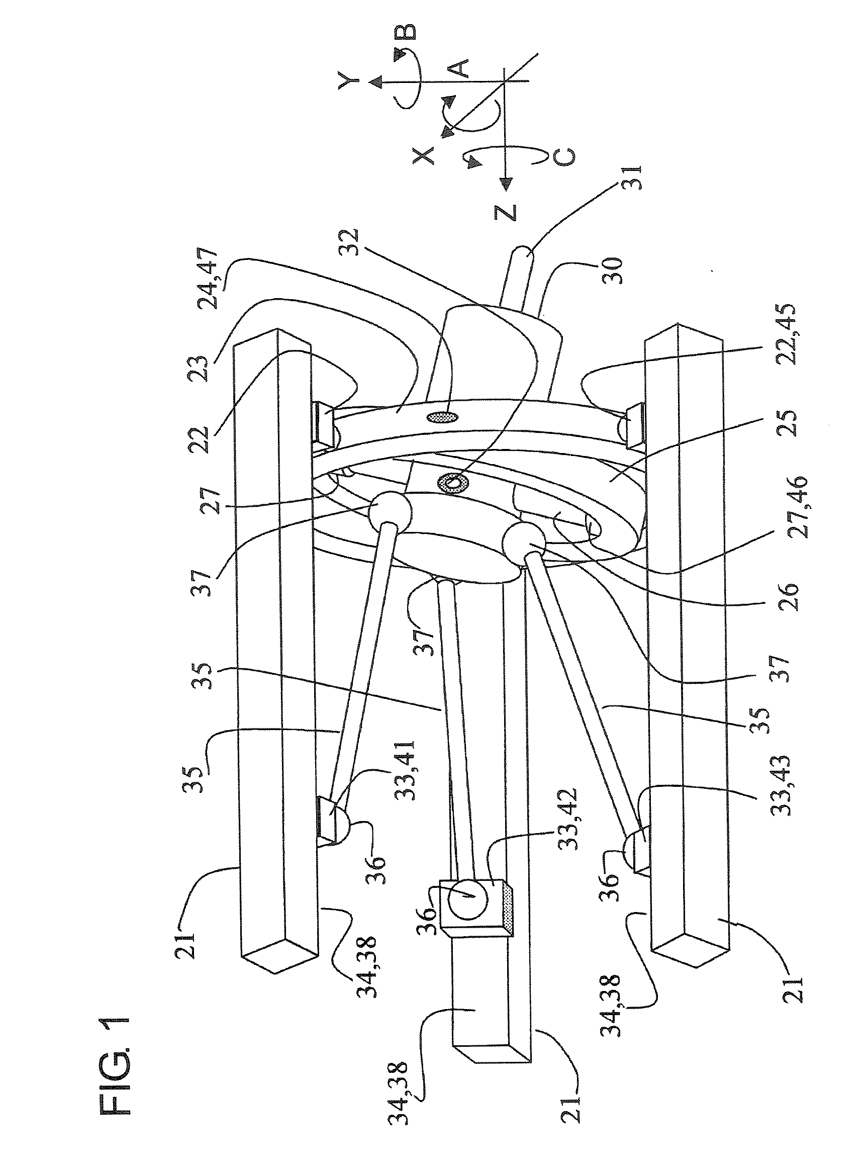
[0033]FIG. 1 is a perspective view of a three degree of freedom parallel mechanism in a first embodiment according to the present invention. Three linear guides 21 are secured to an internal surface of a cylindrical housing such as, e.g., that indicated at 94 in FIG. 9. The three linear guides 21 extend in parallel to one another in a Z-axis direction and are circumferentially arranged at equiangular intervals or at 120-degree intervals about an axis parallel to the Z-axis direction. Three follow sliders 22 are provided and guided along the three linear guides 21 to be movable in the Z-axis direction. An annular first movable support member 23 is secured to the three follower sliders 22. Thus, the first movable support member 23 is movable only in the Z-axis direction. A linear encoder 45 is built in one of the three follower sliders 22 to serve as Z-axis position detector for detecting the Z-axis position of the first movable support member 23.
[0034]A pair of pivot shafts 24 are pr...
second embodiment
[0070]FIG. 7 is a perspective view of a three degree of freedom parallel mechanism in a second embodiment according to the present invention. Components which are the same as those in FIG. 1 are designated by the same reference numerals, and description of such components is omitted for the sake of brevity. In this embodiment, the position and orientation of the spindle head 30 are controlled not by the rods 35 but by three telescopic linear actuators 73. The three telescopic linear actuators 73 are attached to a platform 72 through universal joints 72 each having two degrees of freedom. The platform 72 is a part of a housing which is indicated at 94 in FIG. 9 for example or is a member bodily secured to the housing. Each telescopic linear actuator 73 is provided with a drive servomotor 74 with an encoder (not shown), and an output rod 75 of the actuator 73 is telescopically moved in dependence on the rotational position of the drive servomotor 74 with the encoder. The output rods 7...
third embodiment
[0071]FIG. 8 is a perspective view of a three degree of freedom parallel mechanism in a third embodiment according to the present invention. Components which are the same as those in FIG. 1 are designated by the same reference numerals, and description of such components is omitted for the sake of brevity. In this embodiment, three rotary actuators 82 are attached to a platform 81, which is a part of a housing which is indicated at 94 in FIG. 9 for example or is a member bodily secured to the housing. Each rotary actuator 82 has built therein a rotary encoder for detecting the rotational position of the rotary actuator 82. A first lever 83 is secured to an output end of each rotary actuator 82 to be pivotable bodily with the same. A universal joint 84 having two degrees of freedom is jointed to an end of each first lever 83, and a second lever 85 is connected to the universal joint 84 The second levers 85 are jointed to rear end portions of a spindle head 30 respectively through sph...
PUM
| Property | Measurement | Unit |
|---|---|---|
| Time | aaaaa | aaaaa |
| Angle | aaaaa | aaaaa |
| Angle | aaaaa | aaaaa |
Abstract
Description
Claims
Application Information