Cooling device for fuel cells and motor vehicle equipped with such cooling device

a technology of fuel cell and cooling device, which is applied in the direction of heat exchanger fastening, electrochemical generator, light and heating apparatus, etc., can solve the problems of increasing the total number of required parts of the fuel cell system, and achieve the effect of effectively cooling down the fuel cell system and simplifying the structur

Inactive Publication Date: 2007-10-25
TOYOTA JIDOSHA KK
View PDF6 Cites 33 Cited by
  • Summary
  • Abstract
  • Description
  • Claims
  • Application Information

AI Technical Summary

Benefits of technology

[0019] The present invention is directed to a vehicle equipped with any one of modifications, changes, and alteration of the invention described above. The invention provides a cooling device for fuel cells that has a simplified structure to effectively cool down a fuel cell system. A vehicle equipped with such a cooling device thus exerts the similar effects to those of the cooling device for fuel cells.

Problems solved by technology

This undesirably increases the total number of required parts constituting a fuel cell system.

Method used


Image

  • Cooling device for fuel cells and motor vehicle equipped with such cooling device
  • Cooling device for fuel cells and motor vehicle equipped with such cooling device
  • Cooling device for fuel cells and motor vehicle equipped with such cooling device

Examples


Embodiment Construction

[0027] One mode of carrying out the invention is described below as a preferred embodiment with reference to the accompanied drawings.

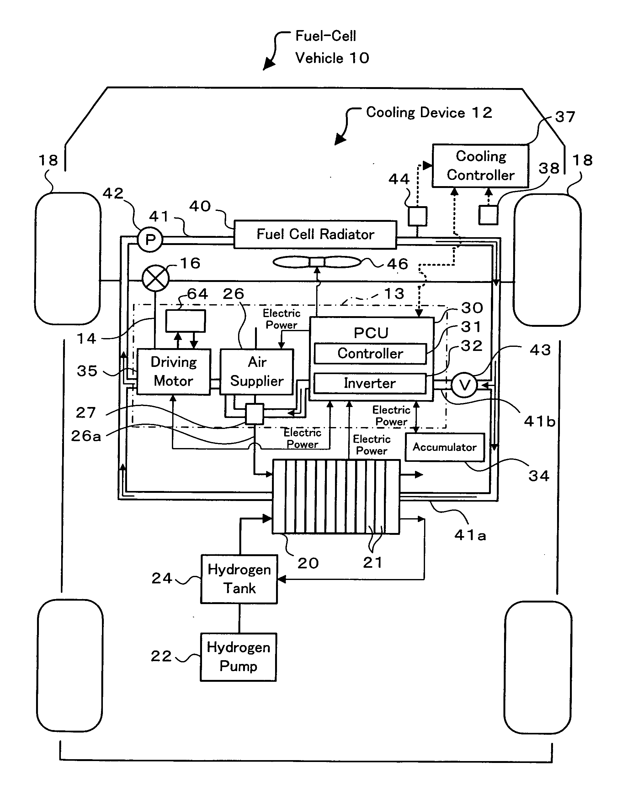
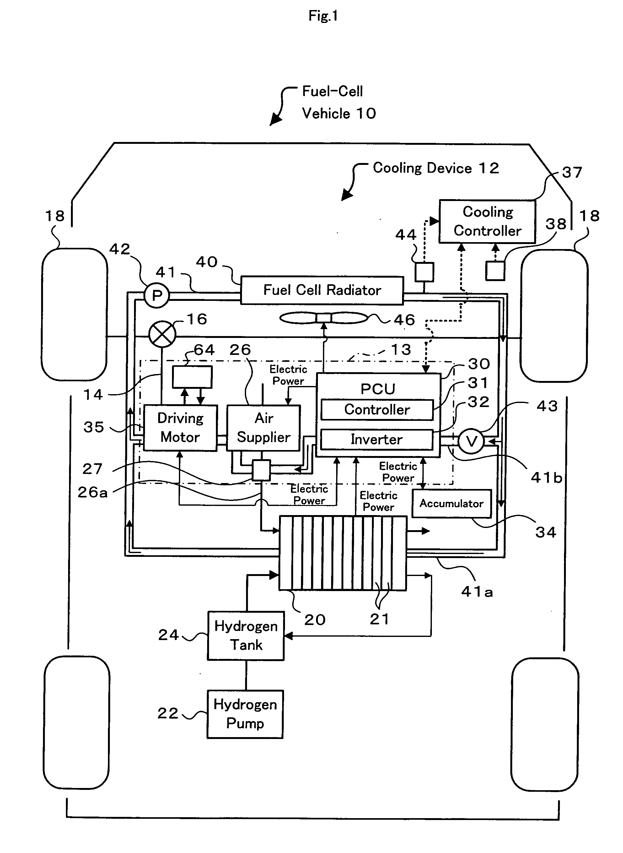
[0028]FIG. 1 is a block diagram schematically illustrating the configuration of a fuel-cell vehicle 10 equipped with a fuel cell system. The fuel cell system mounted on the fuel-cell vehicle 10 includes a stack of fuel cells (hereafter referred to as fuel cell stack) 20 that generates electric power through electrochemical reactions of hydrogen (fuel gas) supplied from a hydrogen tank 22 by means of a hydrogen pump 24 with oxygen included in the air (oxidizing gas) supplied by an air supplier 26, an accumulator 34 that is chargeable with electric power and is dischargeable to supply the accumulated electric power, a driving motor 35 that is activated with electric power to drive and rotate drive wheels 18,18, a power control unit (PCU) 30 that controls the whole fuel cell system, and a cooling device 12 that cools down the fuel cell stack 20 and exot...


PUM

PropertyMeasurementUnit
voltageaaaaaaaaaa
temperatureaaaaaaaaaa
temperature Tfaaaaaaaaaa

Abstract

A cooling water flow path 41 connected with a radiator 40 includes a fuel cell flow path 41a that makes circulation of cooling water from the radiator 40 via a fuel cell stack 20 to the radiator 40, and an exothermic equipment flow path 41b that is placed in parallel to the fuel cell flow path 41a and makes circulation of cooling water from the radiator 40 via exothermic equipment 13 (including an inverter 32 of a power control unit (PCU) 30, an air supplier 26, a heat exchanger 27, and a driving motor 35) to the radiator 40. The multiple pieces of exothermic equipment 13 are arranged in series along the exothermic equipment flow path 41b in the flow direction of cooling water in an ascending order of heat discharge quantity. The inverter 32, the heat exchanger 27, and the driving motor 35 are respectively equipped with a dual cooling mechanism, an air cooling mechanism, and an oil cooling mechanism. The arrangement of the invention ensures stable operations of the respective pieces of exothermic equipment 13 even when the cooling water used for cooling down the exothermic equipment 13 has a higher temperature.

Description

BACKGROUND ART [0001] A proposed cooling device for fuel cells has a first cooling medium flow path that makes the flow of a first cooling medium for cooling down fuel cells, a second cooling medium flow path that makes the flow of a second cooling medium for cooling down exothermic equipment (for example, a driving motor), a radiator that is placed in the second cooling medium flow path and cools down the second cooling medium, and a heat exchanger that attains heat exchange between the first cooling medium and the second cooling medium (see, for example, Japanese Patent Laid-Open Gazette No. 2000-323146). In this proposed cooling device, the second cooling medium cools down the exothermic equipment and is subjected to heat exchange with the first cooling medium. The first cooling medium after the heat exchange cools down the fuel cells. The radiator removes heat from the second cooling medium that is heated up in the process of cooling down the exothermic equipment. This prior art...

Claims


Application Information

Patent Timeline
Patent Type & Authority Applications(United States)
IPC IPC(8): H01M8/12H01M8/00F28F3/12H01M8/02H01M8/04
CPCB60K2001/003B60K2001/005F28D2021/0029F28D2021/0043F28F3/12Y02E60/50H01M8/04029H01M8/04074H01M16/006H01M2250/20Y02T90/32F28F2275/085Y02T90/40Y02E60/10
Inventor HOSHI, JUN
Owner TOYOTA JIDOSHA KK
Why Eureka
Try Eureka