Devices and methods for intravascular drug delivery

a technology of intravascular drug and device, applied in the field of medical devices, can solve the problems of reducing the efficiency of local intravascular drug delivery, maximizing the amount of drug taken up and retained, and drug washout, so as to improve the surface contact area, minimize the injury to the vessel wall, and optimize the effect of agent delivery

Inactive Publication Date: 2007-10-25
ABBOTT CARDIOVASCULAR
View PDF45 Cites 44 Cited by
  • Summary
  • Abstract
  • Description
  • Claims
  • Application Information

AI Technical Summary

Benefits of technology

[0010] The outer surface of the balloon (or other lining member) is separated from the vessel wall by the self-expanding frame therearound. Therefore, similar to the embodiment discussed above having a self-expanding frame of hollow tubes, the catheter operative distal section contacts the vessel wall only with, or primarily with, the relatively thin members of the self-expanding frame. Thus, injury to the vessel wall is minimized. Additionally, the expanded frame pushes into the wall to be at least partially enveloped by the wall in a presently preferred embodiment, to preferably optimize agent delivery. The embedded frame creates channels along the tissue wall which increase the surface contact area between the drug delivery distal section of the catheter and the tissue, and which function as reservoirs to lengthen the drug retention time on the lumen surface.
[0011] As discussed above, the self-expanding frame is configured to contact the vessel wall with the relatively thin hollow tubes or solid members of the frame, and thus minimizes injury to the vessel wall. Consequently, in one embodiment of a method of the invention, a self-expanding frame is slidably displaced in the expanded configuration within the body lumen to directly deliver agent to a longer length of the vessel. Unlike a porous balloon, or other drug delivery system which has a relatively large contact surface area extending around the circumference of the operative distal end of the device, the potential damage caused by moving the thin members of the frame is limited to only a small percentage of the inner circumference of the vessel wall. The method generally comprises advancing within the patient's vessel a catheter which has an elongated shaft having an inner tubular member and an outer sheath member slidably disposed on the inner member, and a self-expanding frame on the distal shaft section fixedly secured to the inner member, the frame being in a radially collapsed configuration within the outer member. The method includes radially expanding the frame into contact with a first section of the vessel wall by slidably displacing the frame relative to the outer member, so that the frame expands to an expanded configuration by release of a radially restraining force of the outer member. Agent is then delivered through a plurality of agent delivery ports along a distal portion of the catheter to deliver agent to the first section of the vessel wall. The method includes slidably displacing the frame in the expanded configuration longitudinally along the vessel to position the expanded frame at a second section of the vessel wall, and flowing agent through the agent delivery ports to deliver agent to the second section of the vessel wall.
[0012] Due to the self-expanding frame, a catheter of the invention has a relatively low profile and high flexibility, which facilitates positioning the operative distal end of the catheter within the vasculature. Although the primary target of the catheter is the proximal two thirds of the diseased coronaries in one embodiment, the catheter can be configured to allow for accessing the tortuous, narrow distal vasculature. In a presently preferred embodiment, a catheter of the invention is configured for delivery of an agent to a coronary artery or vein. However, the vasculature need not be coronary, and can be, for example, renal, femoral, popliteal, carotid, cerebral or other arteries and veins, aneurysms and aneurismal sacs, and may include delivery to implanted devices therein such as grafts, stents and the like. Similarly, agent delivery may occur to the wall of a variety of tubular body lumens including pulmonary, gastrointestinal and urinary tract structures. Thus, the term “vessel” as used herein should be understood to refer generally to body lumens.

Problems solved by technology

One difficulty has been maximizing the amount of drug taken-up and retained at the diseased site, while minimizing the wash-out of large amounts of drug downstream of the treatment site.
Drug wash-out reduces the efficiency of local intravascular drug delivery, in addition to causing potentially harmful systemic exposure to the drug.

Method used


Image

  • Devices and methods for intravascular drug delivery
  • Devices and methods for intravascular drug delivery
  • Devices and methods for intravascular drug delivery

Examples


Embodiment Construction

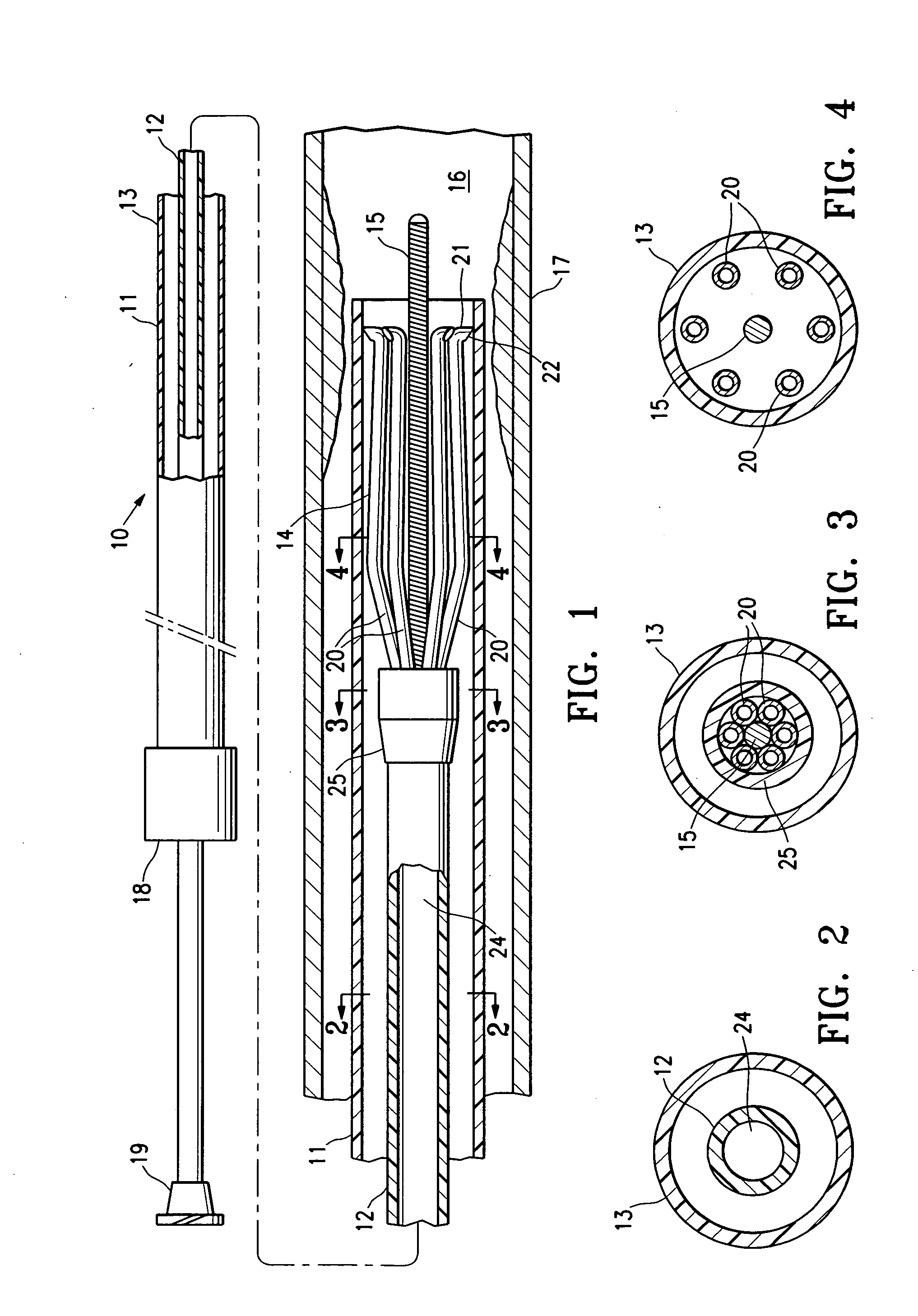
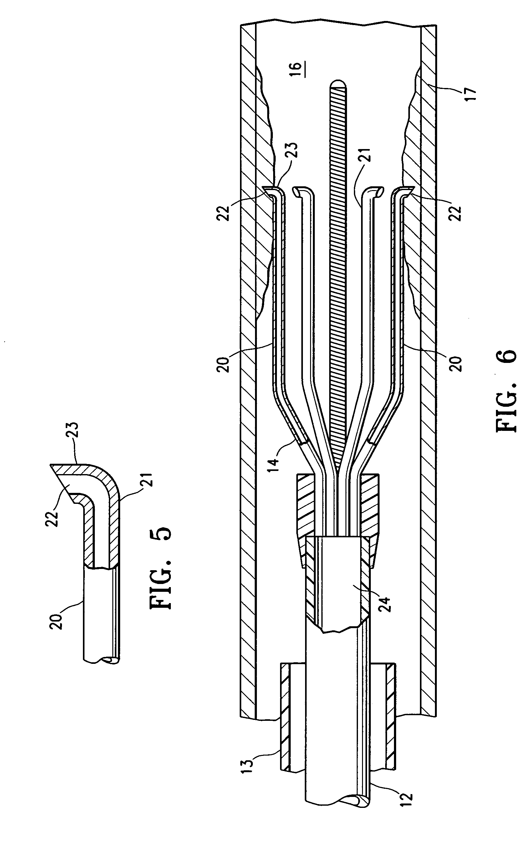
[0025]FIG. 1 illustrates an elevational view, partially in section, of a catheter 10 embodying features of the invention, generally comprising an elongated shaft 11 having an inner tubular member 12 and an outer sheath member 13 slidably disposed on the inner member 12, and a self-expanding frame 14 is on a distal shaft section fixedly secured to the shaft inner member 12 and in a radially collapsed configuration slidably disposed in the outer member 13 of the shaft. A floppy tip distal guide member 15 such as a coil is secured at a distal end of the catheter 10 to facilitate maneuvering the catheter 10 within a patient's body lumen. In the illustrated embodiment, the distal guide member coil 15 has a proximal end secured to the distal end of the inner member 12 and a distal end located distal to the frame 14. In an alternative embodiment, the catheter is configured with a guidewire lumen therein for slidably advancing over a conventional guidewire. FIG. 1 illustrates the catheter 1...


PUM


Abstract

A catheter configured for delivering an agent to a patient's vessel wall, having self-expanding frame, and a method of delivering an agent to a patient's vessel wall. A first catheter has an elongated shaft with an agent delivery lumen and self-expanding frame on a distal shaft section formed of plurality of hollow tubes having joined first ends and free second ends, the free end of each hollow tube having an agent delivery port in fluid communication with the shaft agent delivery lumen and having a hooked tip configured for penetrating the vessel wall in the expanded configuration. Another catheter has a frame around the outer surface of a lining member such as a balloon or a tubular sleeve, such that the frame expanded against the vessel wall and the lining member together define a plurality of pockets between the vessel wall and the outer surface of the lining member.

Description

FIELD [0001] The present invention relates generally to medical devices, and more particularly to a catheter for delivery of an agent to the coronary or peripheral vasculature. BACKGROUND OF THE INVENTION [0002] In the treatment of diseased vasculature, therapeutic agents have commonly been administered, typically as part of other interventional therapies such as angioplasty or stent delivery. Local, as opposed to systemic delivery is a preferred method of treatment in that smaller total levels of medication are administered in comparison to systemic dosages, yet are concentrated at a specific site. As a result, local delivery produces fewer side effects and achieves more effective results. [0003] A variety of methods and devices have been proposed for percutaneous drug delivery to a diseased region of the vasculature. For example, catheters having porous balloons can be used to deliver a therapeutic agent infused into the inflatable interior of the porous balloon and through the po...

Claims


Application Information

Patent Timeline
Patent Type & Authority Applications(United States)
IPC IPC(8): A61M31/00
CPCA61M25/007A61M25/0071A61M25/0074A61M25/0082A61M2025/105A61M25/10A61M2025/0057A61M2025/0096A61M2025/0681A61M25/04
Inventor EL-NOUNOU, FOZAN O.CONSIGNY, PAUL M.LUDWIG, FLORIAN N.
Owner ABBOTT CARDIOVASCULAR
Why Eureka
Try Eureka