Method of rapid insert backing

Inactive Publication Date: 2007-11-01
ACTIVE BURS MOLD & DESIGN
View PDF4 Cites 6 Cited by
  • Summary
  • Abstract
  • Description
  • Claims
  • Application Information

AI Technical Summary

Benefits of technology

[0007]Accordingly, it would be desirable to provide an improved method of manufacturing a reflex insert tool which is less capital intensive, requires less manpower and plating time, less expensive machinery, substantially shortens the cycle time for making a reflex tool all the while maintaining photometric performance. It would also be preferred to utilize a cold spray techn

Problems solved by technology

However, this skin is of insufficient thickness, lacks rigidity, and therefore is unreliable to be used as an insert tool.
Thus, the problem with utilizing the traditional electroforming process and their associated tanks of metal, is that the electroforming process is time consuming and labor intensive.
Moreover, the traditional el

Method used


Image

  • Method of rapid insert backing
  • Method of rapid insert backing
  • Method of rapid insert backing

Examples


Embodiment Construction

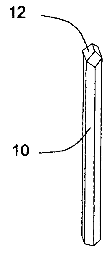
[0025]With respect to FIG. 1, an optical pin 10 has an elongated steel shaft with a precisely machined prism 12 on one end thereof. The prism 12 is specially configured to take on an optical surface configuration which in turn, is imparted onto an electroformed skin.

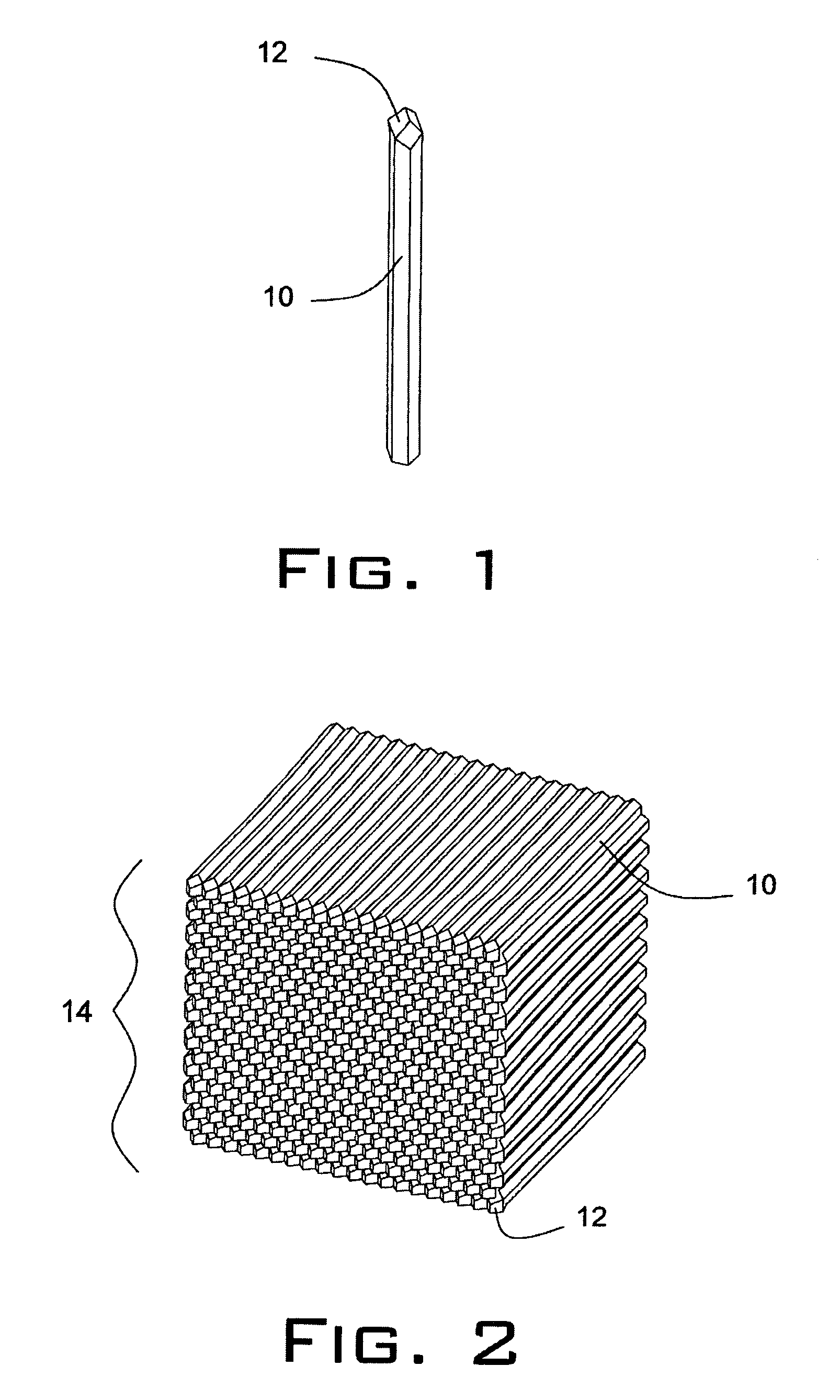
[0026]FIG. 2 illustrates a bundle 14 of optical pins 10 that are arranged together in a predetermined configuration. The configuration illustrated is exemplary in nature and it will be appreciated that the bundles can be arranged in a variety of profiles as desired. The bundle of pins 14 are arranged so as to have the respective prisms adjacent to one another.

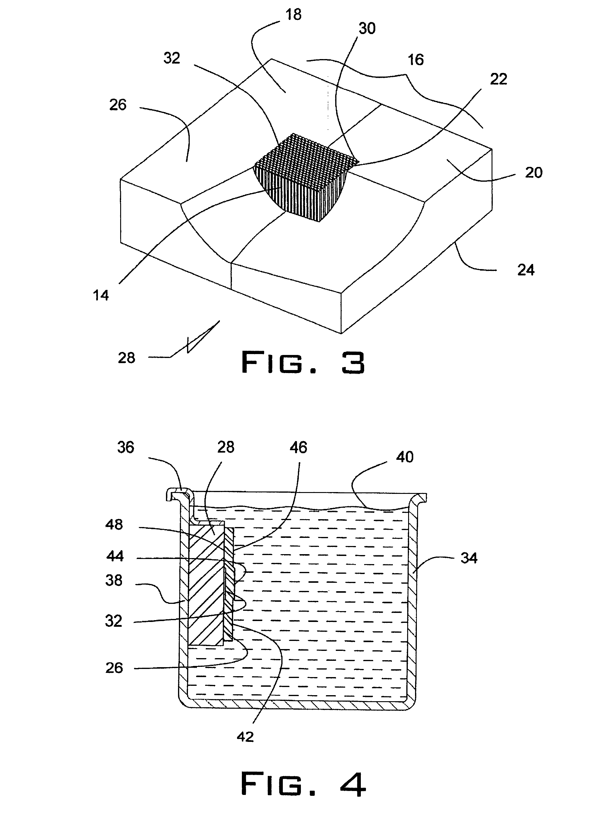
[0027]FIG. 3 illustrates the bundle of pins 14 secured within a two-piece clamp 16. The clamp has a first half 18 and second half 20. The clamp 16 is shown with a cut-away section with the bundle 14 of pins shown positioned within an opening 22 located in the center of the clamp 16. The clamp 16 has a back surface 24 and a front surface 26. The clamp 16 is made pref...


PUM

PropertyMeasurementUnit
Timeaaaaaaaaaa
Timeaaaaaaaaaa
Thicknessaaaaaaaaaa

Abstract

Manufacturing a reflex insert tool includes the steps of assembling optical pins in a bundle, and inserting same into a mold clamp assembly. The mold clamp assembly is placed into a vat, wherein an electroformed skin is developed which in turn is removed from the bath. A cold spraying technique is utilized applying a build up of material on the back surface of the electroformed skin. The back surface of the reflex insert is then machined and through wire EDM, configured to a desired shape and thereafter ready for insertion into a tool for injection molding plastic parts therefrom.

Description

CROSS-REFERENCE TO RELATED APPLICATION[0001]This application claims the benefit of U.S. Provisional Application No. 60 / 796,002, filed 28 Apr. 2006. The disclosure of the above application is incorporated herein by reference.FIELD OF THE INVENTION[0002]The present invention pertains to a method of making a reflex insert tool which in turn is utilized to make an optical plastic part, such as a head lamp, or a tail lamp.BACKGROUND AND SUMMARY OF THE INVENTION[0003]Automobiles routinely have optical components, such as a rear tail light lens, that are manufactured during an injection molding process. Often these plastic parts have reflective elements or prisms built into their surface, in order to aid in the reflectivity of the lens. During the injection molding process, these prisms become part of the tool's surface which results in the negative of the prisms being projected onto an interior surface of the completed plastic part. The present invention focuses on a method of making a re...

Claims


Application Information

Patent Timeline
IPC IPC(8): C25D1/00
CPCC25D1/10C25D1/00
Inventor KENNEY, DANIEL R.
Owner ACTIVE BURS MOLD & DESIGN
Why Eureka
Try Eureka