
Image display apparatus

a display apparatus and image technology, applied in the field of compact, can solve the problems of increasing the display error in the pixel, giving rise to fine particles, and the overall apparatus becomes larger, and achieves the effects of reducing the speckle noise, excellent portability, and high accuracy

Inactive Publication Date: 2007-11-01
PANASONIC CORP
View PDF9 Cites 58 Cited by
  • Summary
  • Abstract
  • Description
  • Claims
  • Application Information

AI Technical Summary

Benefits of technology

[0019]An advantage of the invention is to realize a compact image display apparatus with excellent portability and capable of displaying an image at high accuracy.
[0020]An image display apparatus according to an aspect of the invention includes: a laser light source; a beam scan portion that scans a laser beam emitted from the laser light source; a spatial light modulator that spatially digital-modulates the laser beam scanned by the beam scan portion; and a diffusing member that is disposed between the beam scan portion and the spatial light modulator and diffuses the laser beam scanned by the beam scan portion in a scan direction of the beam scan portion, wherein the beam scan portion scans the laser beam so that an image of one frame is formed by a continuous display of plural fields; and a scan timing of the beam scan portion is synchronized with the light emitting timing of the laser light source.
[0021]According to the image display of the invention, it possible to realize a compact and simple illumination optical system achieving both homogenization and the effect of reducing the speckle noises.

Problems solved by technology

Hence, rays of light projected and scattered on the screen 5111 interfere with one another randomly, which gives rises to speckle noises like fine particles.
In addition, because the homogeneous illumination optical system occupies a large volume and the diffusing plate oscillation means 5113 is separately necessary for reducing the speckle noises, there arises a problem that the overall apparatus becomes larger.
However, the latter field sequential method excels in terms of space saving and the number of components (cost).
However, in the 2D image display apparatus using the laser as described above, in a case where the laser light source is lit ON by the field sequential method using the spatial light modulator described above and the scan mirror, problems, such as an increase of a display error in a pixel, contrast deterioration, and noises like a sandstorm, are known to occur in pixels expressing the halftone.
These problems possibly become factors that interfere with the realization of the field sequential method that is essential in realizing a compact image display apparatus with excellent portability.
However, the field sequential method requires a spatial light modulator with a high display rate.
Hence, no consideration is given to a reduction of speckle noises, which makes it impossible to achieve a high-quality image.
However, because the ferroelectric liquid crystal element described above displays the grayscale by the time width modulation, there may be a case where it fails to display the grayscale appropriately depending on the timing of a beam scan and a pixel display.
However, a spatial light modulator capable of performing the analog grayscale display has so slow a display rate that it is not suitable for the field sequential method.
In short, it is difficult to realize the field sequential method.

Method used


Image

  • Image display apparatus
  • Image display apparatus
  • Image display apparatus

Examples


first embodiment

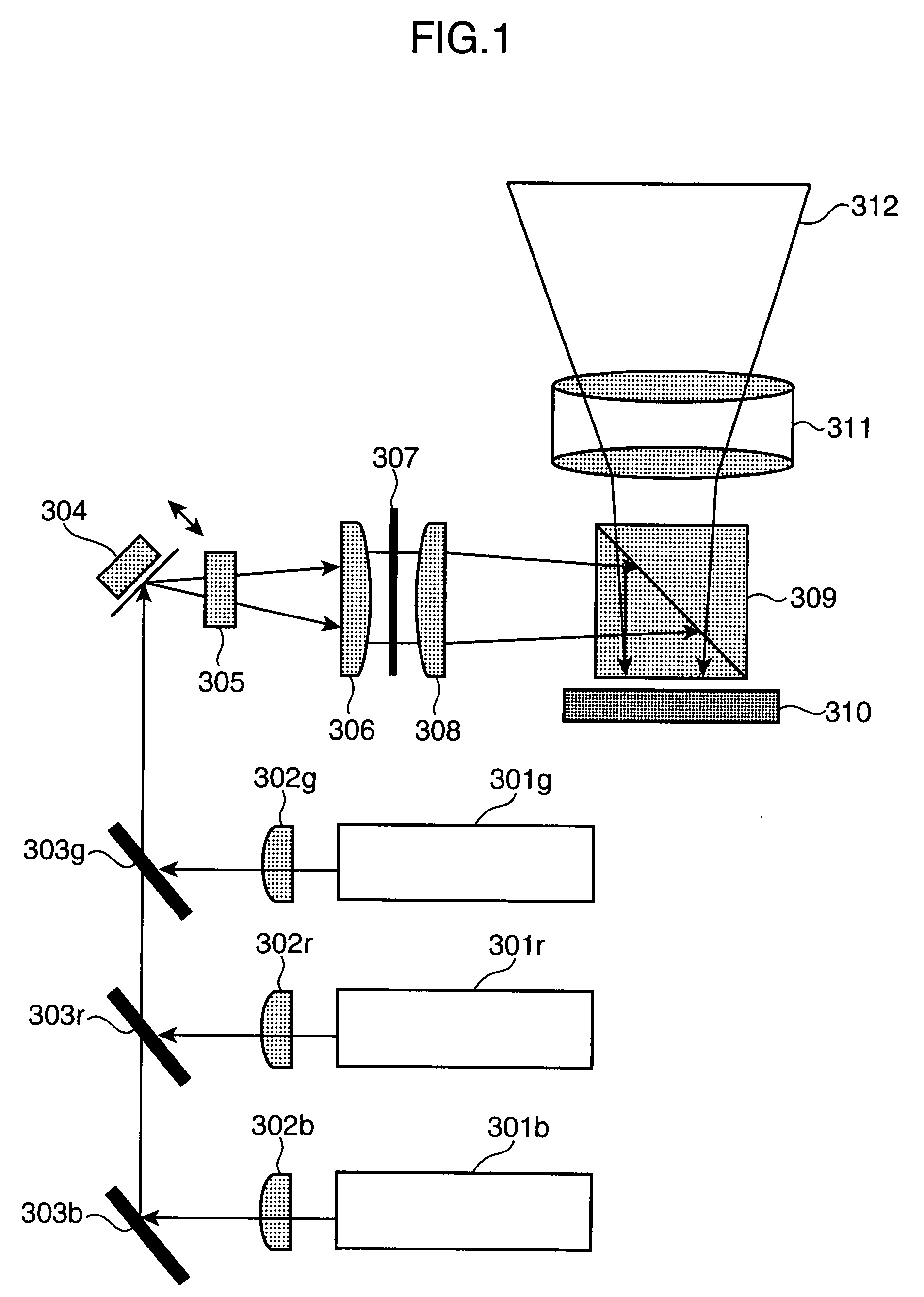
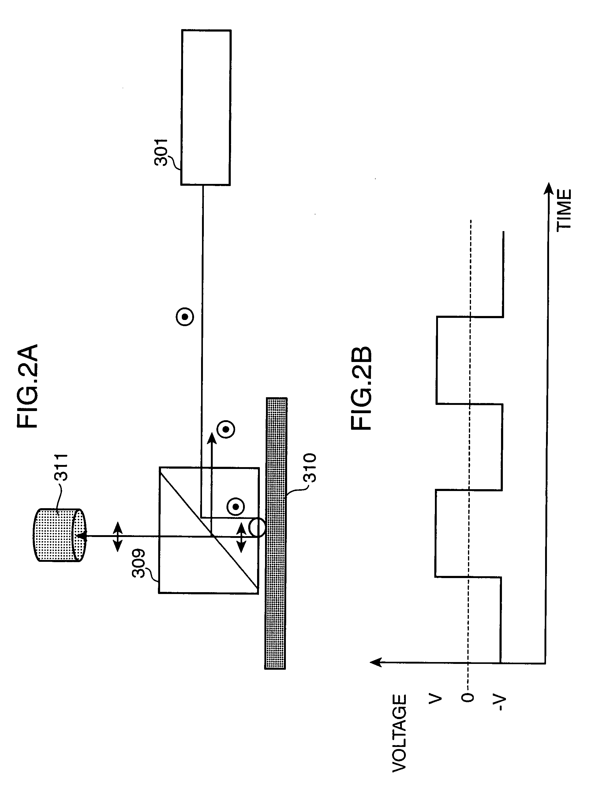
[0068]The configuration of a 2D image display apparatus according to a first embodiment of the invention is shown in FIG. 1. The 2D image display apparatus of this embodiment includes a blue laser light source 301b, a red laser light source 301r, a green laser light source 301g, collimate lenses 302b, 302r, and 302g, mirrors 303b, 303r, and 303g, a scan mirror 304, a cylindrical lens 305, a relay lens 306, a diffusing plate 307, a field lens 308, a prism 309, a 2D spatial light modulator 310, a projection lens 311, and a screen 312. This embodiment will describe a case where a liquid crystal on silicon (LCOS) is used as the 2D spatial light modulator 310. It goes without saying, however, that the 2D spatial light modulator 310 of this embodiment is not limited to the LCOS.

[0069]Rays of laser light emitted from the blue laser light source 301b, the red laser light source 301r, and the green laser light source 301g are collimated to rays of parallel light by the collimate lenses 302r,...

second embodiment

[0087]A second embodiment of the invention will now be described. In this embodiment, an auto power control (APC) that automatically controls, an output of the semiconductor laser is applied to the 2D image display apparatus of the first embodiment described above. The “droop” occurring when rays of light are emitted sequentially from the semiconductor lasers is improved by automatically controlling outputs of the semiconductor lasers. The configuration of a 2D image display apparatus of this embodiment is shown in FIG. 11.

[0088]The 2D image display apparatus of FIG. 11 is the same as the first embodiment described above in that an LCOS is used as the 2D spatial light modulator 310. In the 2D image display apparatus of this embodiment, outputs from the red, green, and blue semiconductor lasers 301r, 301g, and 301b are monitored by photo detectors 1301r, 1301g, and 1301b, respectively. The photo detectors 1301r, 1301g, and 1301b feed back monitor signals 1303 to the laser current sou...

third embodiment

[0091]A third embodiment of the invention will now be described. A 2D image display apparatus according to this embodiment of the invention is an embodiment where a second harmonic of a fiber laser is used as the green semiconductor laser light source in the first and second embodiments described above. FIG. 14 shows the configuration of a fiber laser used as the green semiconductor laser of the 2D image display apparatus of this embodiment.

[0092]Laser light emitted from an exciting (pumping) LD 1501 is let go incident on a rear-earth-doped clad pump fiber 1503, which is a laser medium, and the laser light starts to oscillate as it is resonated inside a laser resonator formed of fiber gratings 1502 and 1504, which are reflection mirrors. A polarizer 1505 is inserted in order to direct the oscillated laser light to a single polarization direction. The fiber laser has a good beam quality, and is able to define the oscillation wavelength spectrum to the line width of reflection spectru...


PUM

PropertyMeasurementUnit
angle of diffusionaaaaaaaaaa
wavelengthaaaaaaaaaa

Abstract

A 2D image display apparatus using a laser light source. By controlling the timing of a scan by a beam scan portion in response to the characteristic of a laser light source and by setting a light emitting time of the laser light source to an integral multiple of a scan cycle of the beam scan portion, it is possible to illuminate a spatial light modulator homogeneously with a laser beam. It is thus possible to display an image at high accuracy without causing a bright line, irregularities in brightness, and contrast deterioration.

Description

BACKGROUND OF THE INVENTION[0001]1. Field of the Invention[0002]The present invention relates to an image display apparatus, such as a video projector, a TV receiver, and a liquid crystal panel, and more particularly, to a compact image display apparatus suitable for portable use.[0003]2. Background Art[0004]There is a laser realized by combining laser light sources for red, green, and blue that are reduced in size and achieve high luminous efficiencies, and a spatial light modulator such as a liquid crystal element, a scan mirror and a micro mirror, and an image display apparatus using this laser as a light source has been actively developed in recent years. Because the laser is monochromatic, the image display apparatus described above is able to have a color reproduction range 1.2 to 1.7 times wider than that of conventional liquid crystal display projector using color filters, CRT using a fluorescent material, and plasma display, etc. Further, because laser light is readily focu...

Claims


Application Information

Patent Timeline
Patent Type & Authority Applications(United States)
IPC IPC(8): H04N9/12G02F1/1335
CPCH04N9/3129G02B27/48
Inventor FURUYA, HIROYUKIMIZUUCHI, KIMINORIYOKOYAMA, TOSHIFUMIITOH, TATSUOKUROZUKA, AKIRAYAMAMOTO, KAZUHISA
Owner PANASONIC CORP
Learn More