Narrow bandpass filter assemblies for solar telescopes

a filter assembly and solar telescope technology, applied in the field of narrow bandpass filter assembly for solar telescopes, can solve the problems of increasing loss, increasing the cost of filter assembly construction, and increasing the safety, stability and physical construction of the filter assembly, so as to achieve low cost, high efficiency, and low transmittance.

Active Publication Date: 2007-11-01
HRUSKA CURTIS ROSS
View PDF25 Cites 13 Cited by
  • Summary
  • Abstract
  • Description
  • Claims
  • Application Information

AI Technical Summary

Benefits of technology

[0019] The preferred embodiments of the invention relate to the combination of lower transmittance etalons with higher transmittance filters, including a single circular polarizer with high efficiency for its filtered polarization, to achieve necessary throughput of a narrow bandpass region. Preferably, the etalon has transmittance of less than 25%, and a bandwidth of less than 0.15 nm. The lower transmittance etalons can be achieved by using lower transmittance solid-state etalon materials, or by control of multiple coatings on the etalon. The circular polarizer is produced by combining a quarter-wave plate with a linear polarizing element that has a contrast ratio of at 500:1 and an optical performance of at least 85% for its filtered plane of polarization along the optical path of the filter assembly. In preferred embodiments, the linear polarizing element is an absorptive-type or reflective-type linear polarizer. In other preferred embodiments, the linear polarizing element of the circular polarizer may be a reflective / transmissive-type polarizer, such as polarizing beamsplitters or wire-grid polarizers. The quarter-wave plate of the circular polarizer may be optionally achromatic. These alternate embodiments describe filter combinations that reduce the optical assembly's footprint, and provide additional methods to remove stray light.

Problems solved by technology

Optical filter assemblies for telescopes have demanding requirements for stability as well as optical quality, due to the fact that long viewing times are often employed to observe quiescent solar features.
This places additional demands on the safety, stability and physical construction of the filter assemblies.
Second, many events of interest, such as solar flares or filaments, are transient, and would be lost against the bright background signal of the solar luminance without additional filtering.
Spacer layers are employed to further narrow the bandpass, but deposited spacer layers can become increasingly lossy, and affect the overall performance of the filter.
In practice, the difficulty is to maintain this desired distance, and therefore the spectral position of the narrow bandpass filter, in the face of barometric pressure changes, temperature changes, or even typical transport or alignment changes as one tracks across the sky.
In addition, the coated plates are typically extremely thin optical materials and therefore fragile.
Such control systems add complexity, bulk and cost, and may have slow response times to changing conditions.
However, one can easily understand that significant expense, skill and time may be required to create a spacer of sufficient flatness, transmission and purity to support the reflector layers.
In addition, if the manufactured bandpass is even fractionally off-alignment from the wavelength of interest, the etalon must be physically tilted to change the effective pathlength through the filter, and this may alter its aperture or aspect ratio in an optical assembly.
Often solid-state etalons suffer from absorption losses due to impurities or irregularities in the crystal structure, or to their inherent optical properties.
For instance, while mica cleaves cleanly along parallel crystal plates, it is difficult to control reproducibly, and may contain inclusions.
Unfortunately, such synthesis is typically accompanied by higher costs.
Too much filtering may isolate the exact bandpass desired, but not with enough intensity for viewing.
Too little filtering and the signal is lost in the high background noise of the solar spectrum.
Furthermore, the viewer or detector can be irreparably harmed by excess radiation.
Thus, such telescopes have unique and demanding requirements for careful filtering.

Method used


Image

  • Narrow bandpass filter assemblies for solar telescopes
  • Narrow bandpass filter assemblies for solar telescopes
  • Narrow bandpass filter assemblies for solar telescopes

Examples


example 1-3

[0085] The transmittance and bandwidth characteristics of each element, and of the combined optical assembly, were measured on a custom-built high-resolution spectrophotometer with a resolving power of 0.0023 nm. The spectrophotometer was calibrated for wavelength accuracy using both hydrogen and deuterium atomic emission line sources.

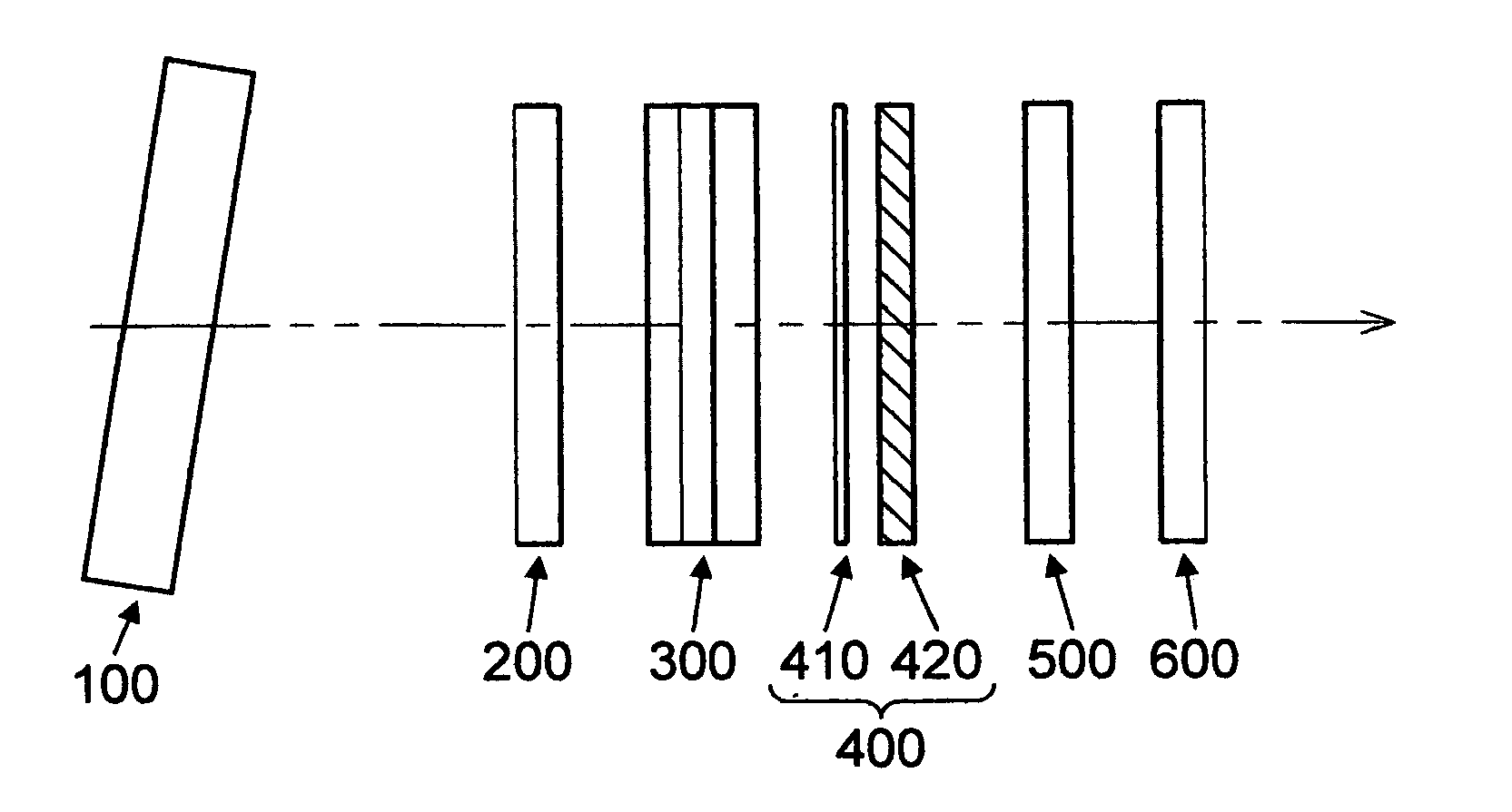
[0086] The optical assembly outlined in FIG. 1 was created with the optical elements described below, in their order of assembly from the light entrance path. In these examples, all elements were joined with an optical couplant.

[0087] A pre-filter with a measured transmittance of 94%, consisting of Schott RG610 glass coated on the entry surface with a broadband AR with a minimum in reflectance centered at 656.3 nm, and on the exit surface with a dichroic heat reflector with cutoff from 715 nm to beyond 1 micron.

[0088] A broadband AR (bandwidth of 430-680 nm, with a measured reflectance of 0.25% at 656 nm).

[0089] A blocker / trimmer filter consisting ...

examples 6-10

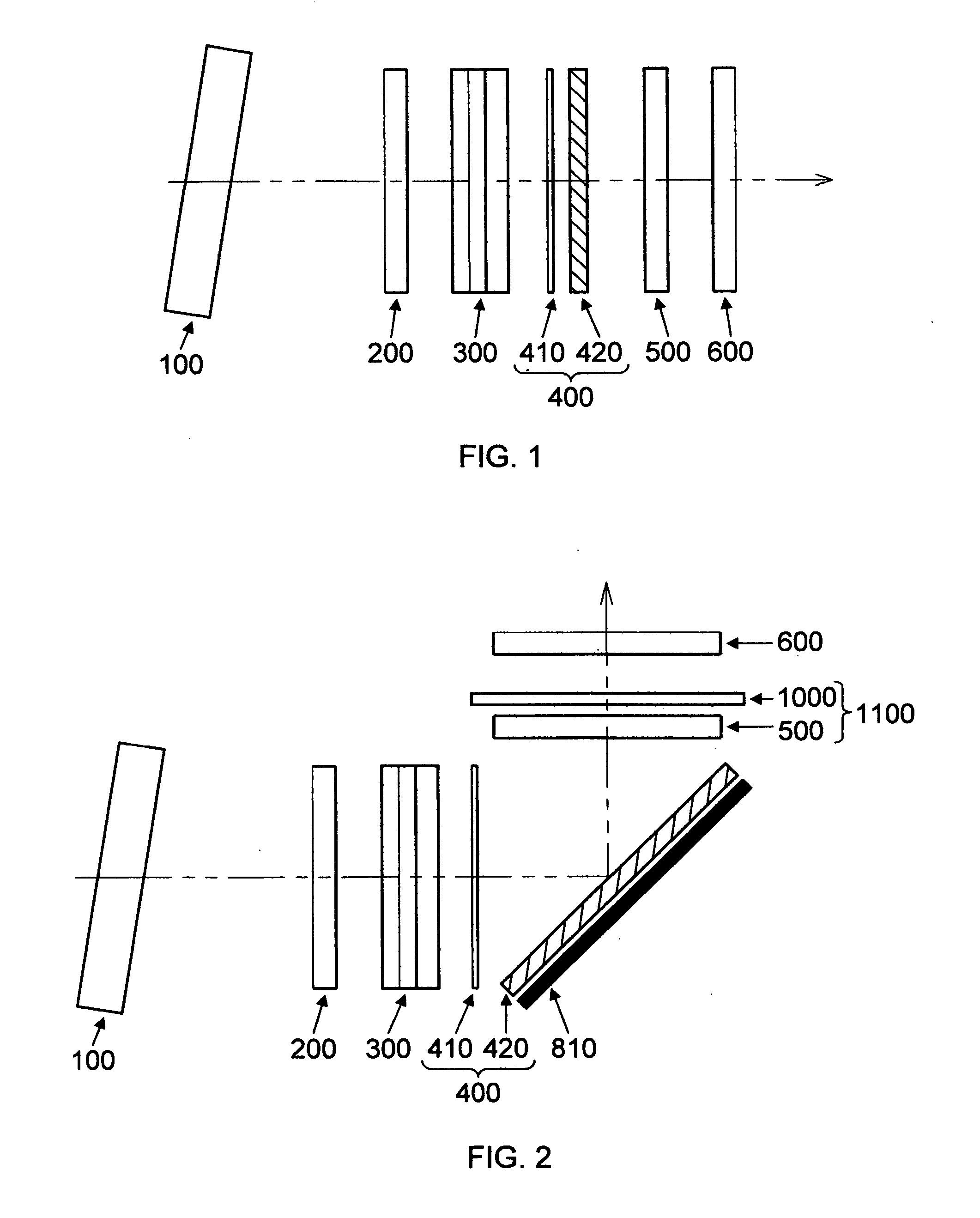
[0094] These are theoretical examples illustrating the use of a polarizing beamsplitter, in the configuration of optical elements outlined in FIG. 2.

[0095] Using the following optical elements:

[0096] Pre-filter with Transmittance of 94%, as described in examples 1-3.

[0097] AR filters at the entrance and exit of the optical path, with reflectance of 0.25% at 656 nm, as in Examples 1-3.

[0098] Blocker / trimmer filter with transmittance of 50% and FWHM of 1.3 nm, as described in Examples 1-3, or alternately, a theoretical blocker / trimmer filter with a FWHM of 1.0 nm and theoretical transmission of 45%.

[0099]λ / 4 plate with a 164 nm retardance value.

[0100] Polarizing beamsplitter cube with 94% theoretical reflection for the p-state.

[0101] Three absorbing, ruby red mica etalons, with different bandpass widths and transmittance values, as described in Examples 1-3, or alternately, theoretical lower transmittance etalons with the same bandwidth and transmittance values.

[0102] The expe...

examples 11-13

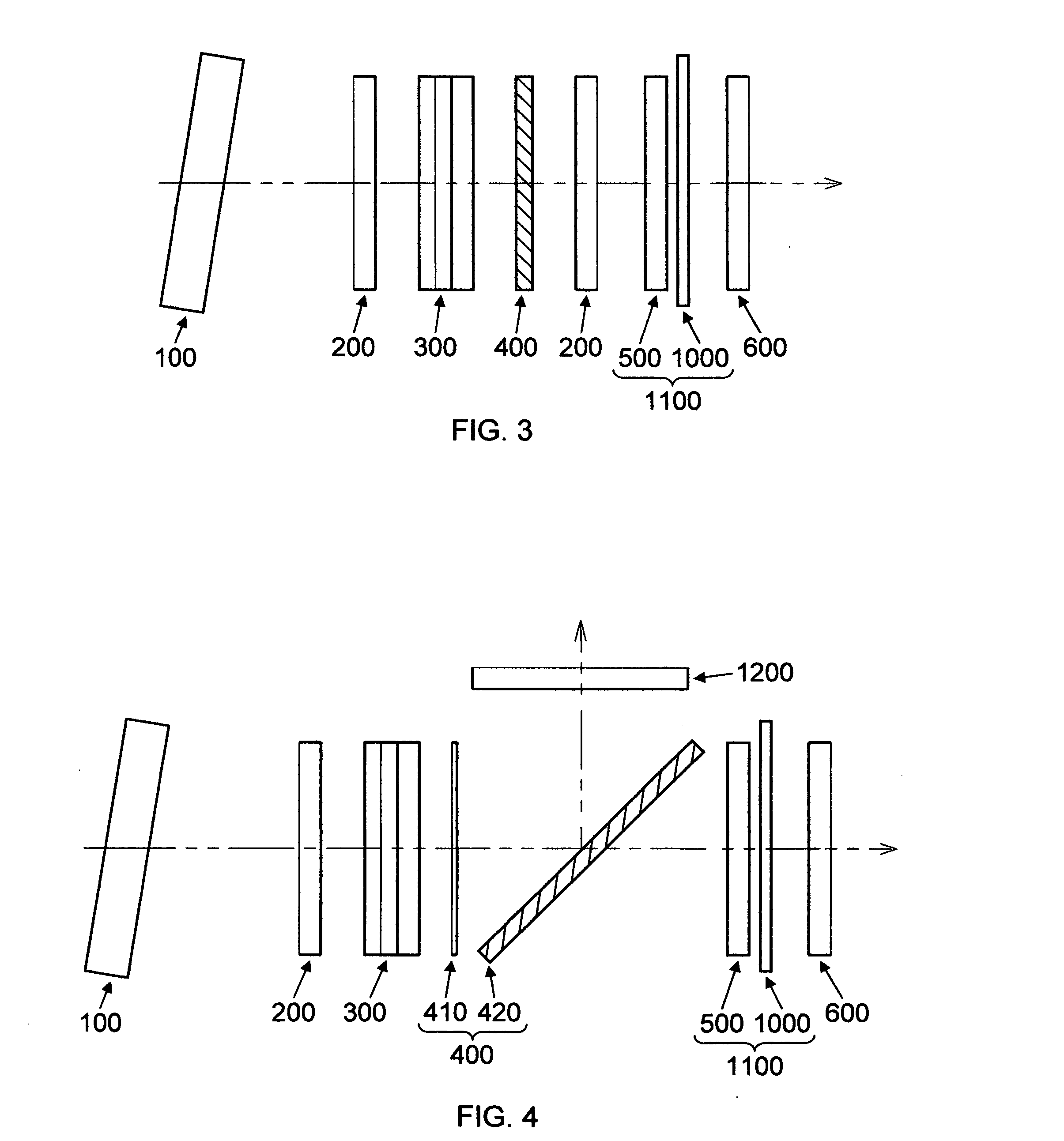
[0103] The following theoretical examples illustrate the use of the heated etalon construct outlined in FIG. 3. The optical elements for these Examples are as follows:

[0104] Pre-filter with Transmittance of 94%, as described in Examples 1-3.

[0105] AR filters at the entrance and exit of the optical path, and just before the heated etalon construct, each with reflectance of 0.25% at 656 nm, as described in Examples 1-3.

[0106] Blocker / trimmer filter with transmittance of 50% and FWHM of 1.3 nm, as described in Examples 1-3.

[0107] Achromatic circular polarizer with transmittance of 88.2%, as described in Examples 1-3.

[0108] Three theoretical absorbing mica or controlled lower transmittance etalons, with one side coupled to the thermally conductive optical element, and one side exposed to air. Coupling eliminates one air interface and therefore results in slightly higher transmission and slightly wider bandpasses for any given starting design.

[0109] Thermally conductive optical ele...


PUM


Abstract

The invention relates to the combination of lower transmittance etalons with higher transmittance filters, including use of a single circular polarizer with high efficiency and optical performance for its filtered polarization, to achieve necessary throughput of a narrow bandpass region. The lower transmittance etalons can be achieved by using lower transmittance solid-state etalon materials, or by control of the coatings on the etalon. Alternate configurations are described that reduce the optical assembly's footprint, and/or include additional filters to remove stray light. An innovative option to heat the etalon directly is disclosed to actively stabilize and maintain the etalon's bandpass.

Description

CROSS-REFERENCE TO RELATED APPLICATIONS [0001] Not Applicable STATEMENT REGARDING FEDERALLY SPONSORED RESEARCH OR DEVELOPMENT [0002] Not Applicable THE NAMES OF THE PARTIES TO A JOINT RESEARCH AGREEMENT [0003] Not Applicable REFERENCE TO A SEQUENCE LISTING [0004] Not Applicable. BACKGROUND OF THE INVENTION [0005] Interest in telescopes continues to increase as both professional and amateur astronomers make new discoveries. Optical filter assemblies for telescopes have demanding requirements for stability as well as optical quality, due to the fact that long viewing times are often employed to observe quiescent solar features. This places additional demands on the safety, stability and physical construction of the filter assemblies. [0006] Solar telescopes have the additional requirement that discrete, weak signals must be discriminated against an extremely bright background. First, this is needed to protect the eyes of the viewer, or to avoid saturation and overload of a detector. S...

Claims


Application Information

Patent Timeline
Patent Type & Authority Applications(United States)
IPC IPC(8): G02B5/28
CPCG02B5/284
Inventor HRUSKA, CURTIS ROSS
Owner HRUSKA CURTIS ROSS
Why Eureka
Try Eureka