Eureka AIR delivers breakthrough ideas for toughest innovation challenges, trusted by R&D personnel around the world.

Technique for forming a silicon nitride layer having high intrinsic compressive stress

a silicon nitride and intrinsic compressive stress technology, applied in the microstructure field, can solve the problems of increasing the defect rate at stress levels above 1.5 gpa, etc., and achieves the effect of reducing the defect rate of silicon nitride, high intrinsic compressive stress, and increasing the amount of compressive stress

Inactive Publication Date: 2007-11-01
ADVANCED MICRO DEVICES INC
View PDF4 Cites 6 Cited by
  • Summary
  • Abstract
  • Description
  • Claims
  • Application Information

AI Technical Summary

Benefits of technology

The present invention is about a technique for making silicon nitride with high compressive stress using a PECVD process. By controlling the deposition atmosphere with both high-frequency and low-frequency power, the technique reduces defects and achieves higher levels of compressive stress compared to conventional methods. This results in improved performance of transistors, particularly in terms of drive current capability. The method involves creating a plasma in a silane-containing atmosphere using high-frequency power and low-frequency power, adjusting the ion bombardment towards the substrate surface, and depositing silicon nitride with the desired compressive stress. The resulting transistor element has a compressively stressed silicon nitride material near the gate electrode structure, with the amount of compressive stress controlled by the amount of high-frequency power and low-frequency power supplied to the deposition atmosphere.

Problems solved by technology

By establishing the deposition atmosphere and thus the acceleration potential for increasing the ion bombardment during the deposition phase on the basis of a low-frequency power, significantly increased amounts of compressive stress may be obtained compared to conventional techniques, which substantially rely on a single frequency excitation and biasing power, which may cause an increased defect rate at stress levels above 1.5 GPa.

Method used


Image

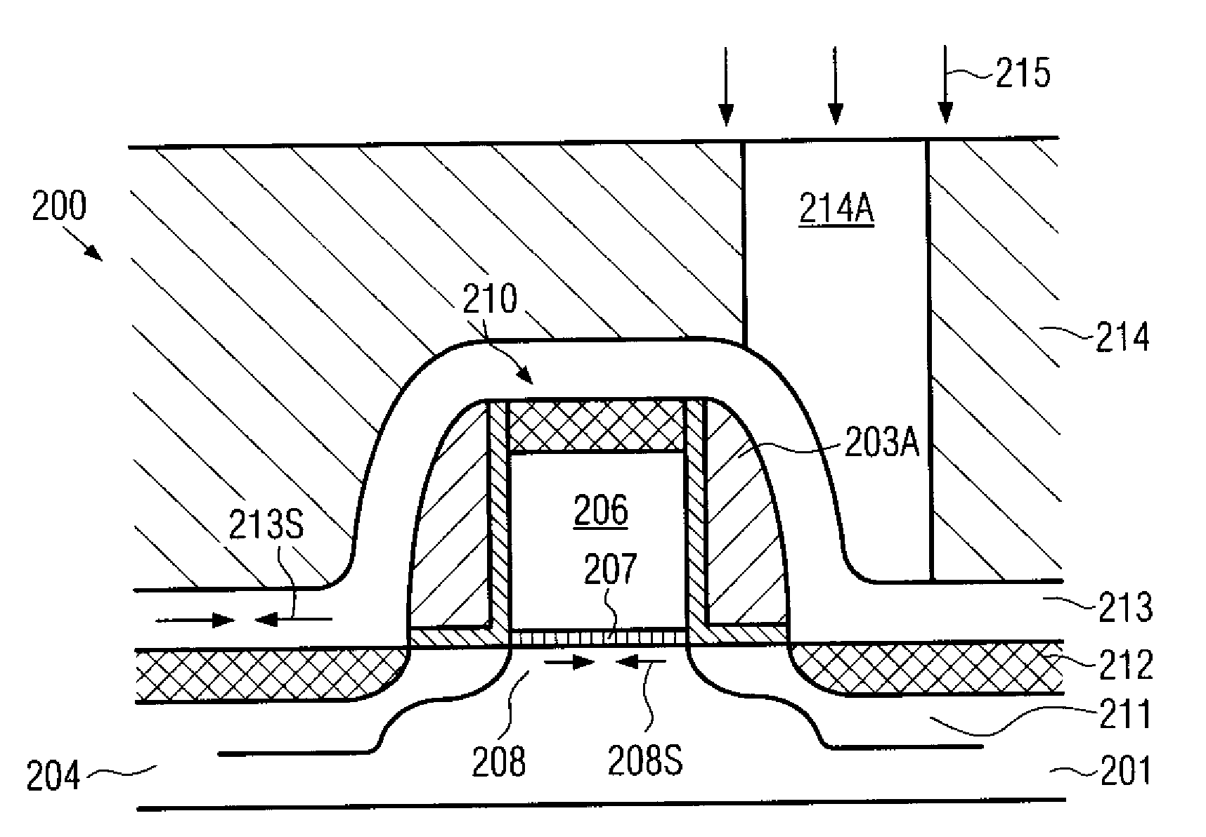
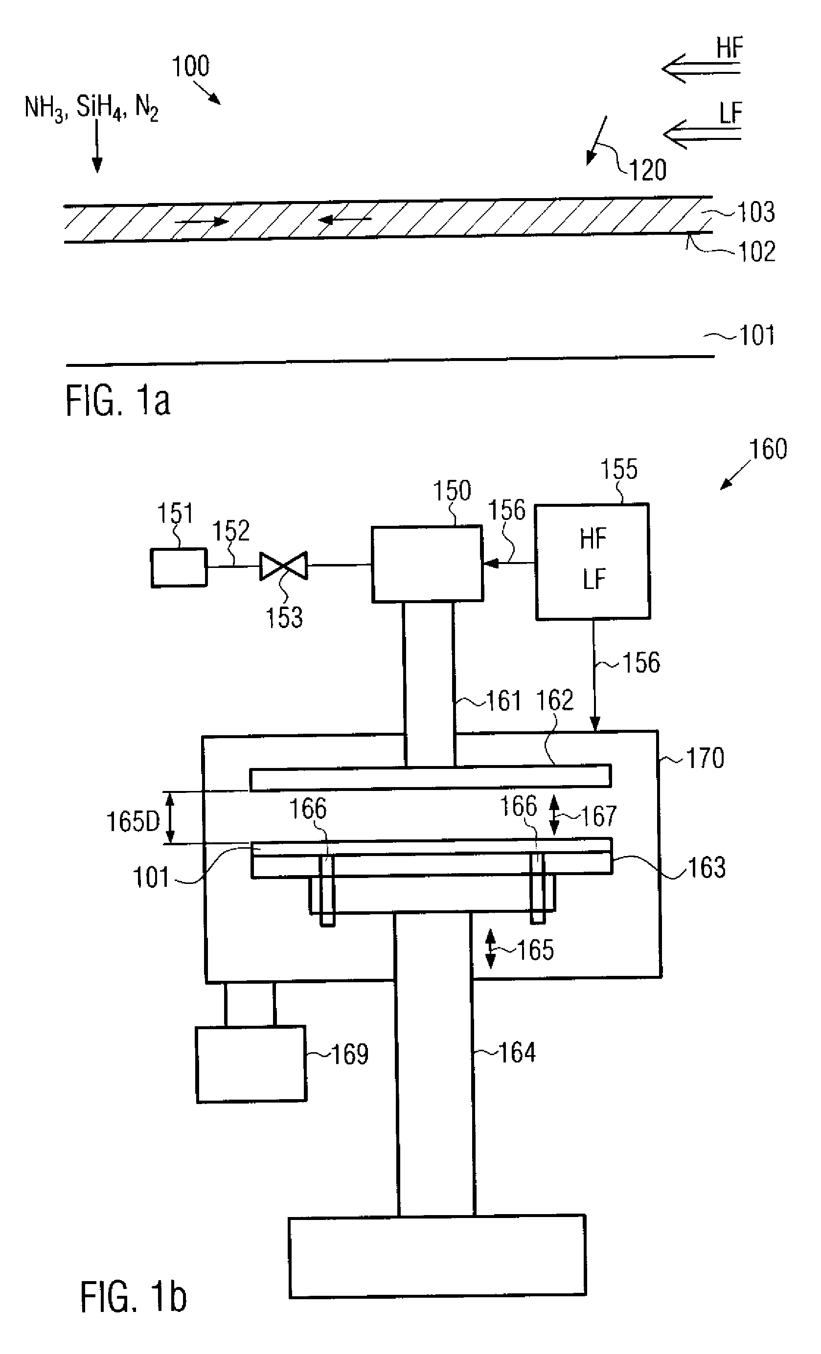
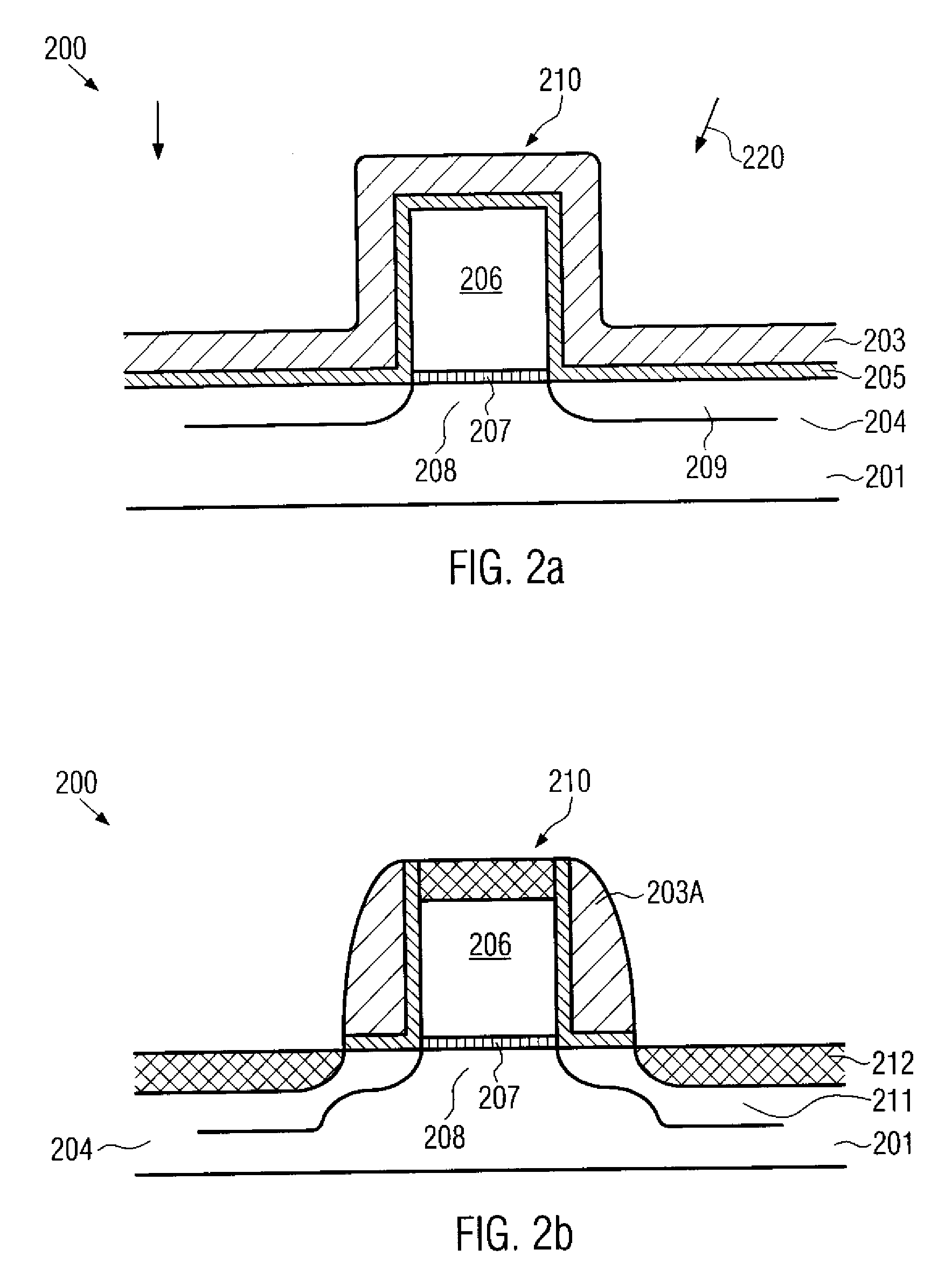
  • Technique for forming a silicon nitride layer having high intrinsic compressive stress
  • Technique for forming a silicon nitride layer having high intrinsic compressive stress
  • Technique for forming a silicon nitride layer having high intrinsic compressive stress

Examples


Embodiment Construction

[0020]Illustrative embodiments of the invention are described below. In the interest of clarity, not all features of an actual implementation are described in this specification. It will of course be appreciated that in the development of any such actual embodiment, numerous implementation-specific decisions must be made to achieve the developers' specific goals, such as compliance with system-related and business-related constraints, which will vary from one implementation to another. Moreover, it will be appreciated that such a development effort might be complex and time-consuming, but would nevertheless be a routine undertaking for those of ordinary skill in the art having the benefit of this disclosure.

[0021]The present invention will now be described with reference to the attached figures. Various structures, systems and devices are schematically depicted in the drawings for purposes of explanation only and so as to not obscure the present invention with details that are well ...


PUM

PropertyMeasurementUnit
temperatureaaaaaaaaaa
pressureaaaaaaaaaa

Abstract

By forming a compressively stressed silicon nitride material on the basis of a mixed frequency plasma-enhanced chemical vapor deposition (PECVD) process, a higher compressive stress may be achieved at a reduced defect rate compared to conventional single frequency processes. Consequently, a more efficient strain-inducing mechanism for P-channel transistors and a corresponding increase of performance may be accomplished.

Description

BACKGROUND OF THE INVENTION[0001]1. Field of the Invention[0002]Generally, the present invention relates to the field of microstructures, such as integrated circuits, and, more particularly, to the formation of a silicon nitride layer having a high intrinsic compressive stress.[0003]2. Description of the Related Art[0004]The fabrication of microstructures, such as integrated circuits, requires the formation of a large number of circuit elements or other elements on a given chip area according to a specified layout. For this purpose, different types of material layers have to be formed and frequently patterned or otherwise modified to obtain desired material properties in a highly localized manner. For instance, conductive, semiconductive and insulating materials may have to be formed at well-defined locations within a chip area in order to accomplish a desired functional behavior of the element under consideration. Moreover, certain materials are primarily used for enhancing the pat...

Claims


Application Information

Patent Timeline
Patent Type & Authority Applications(United States)
IPC IPC(8): H01L21/31
CPCC23C16/345C23C16/505C30B25/16C30B29/38H01L29/7843H01L29/665H01L29/6656H01L29/6659H01L29/7833H01L21/3185H01L21/02274H01L21/02211H01L21/0217
Inventor BAER, STEFFENHOHAGE, JOERGKAHLERT, VOLKER
Owner ADVANCED MICRO DEVICES INC
Why Eureka
Eureka Blog
Learn More