Gas Chromatograph

a gas chromatograph and chromatograph technology, applied in the field of gas chromatographs, can solve the problems of reduced separation, false positive identification, and unsuitable for fast real-time monitoring, and achieve the effect of improving the chemical separation power of chemical detectors and excellently solving problems

a gas chromatograph and chromatograph technology, applied in the field of gas chromatographs, can solve the problems of reduced separation, false positive identification, and unsuitable for fast real-time monitoring, and achieve the effect of improving the chemical separation power of chemical detectors and excellently solving problems

US20070256474A1Inactive Publication Date: 2007-11-08ENVIRONICS

Image

  • Gas Chromatograph
  • Gas Chromatograph
  • Gas Chromatograph

Examples


Embodiment Construction

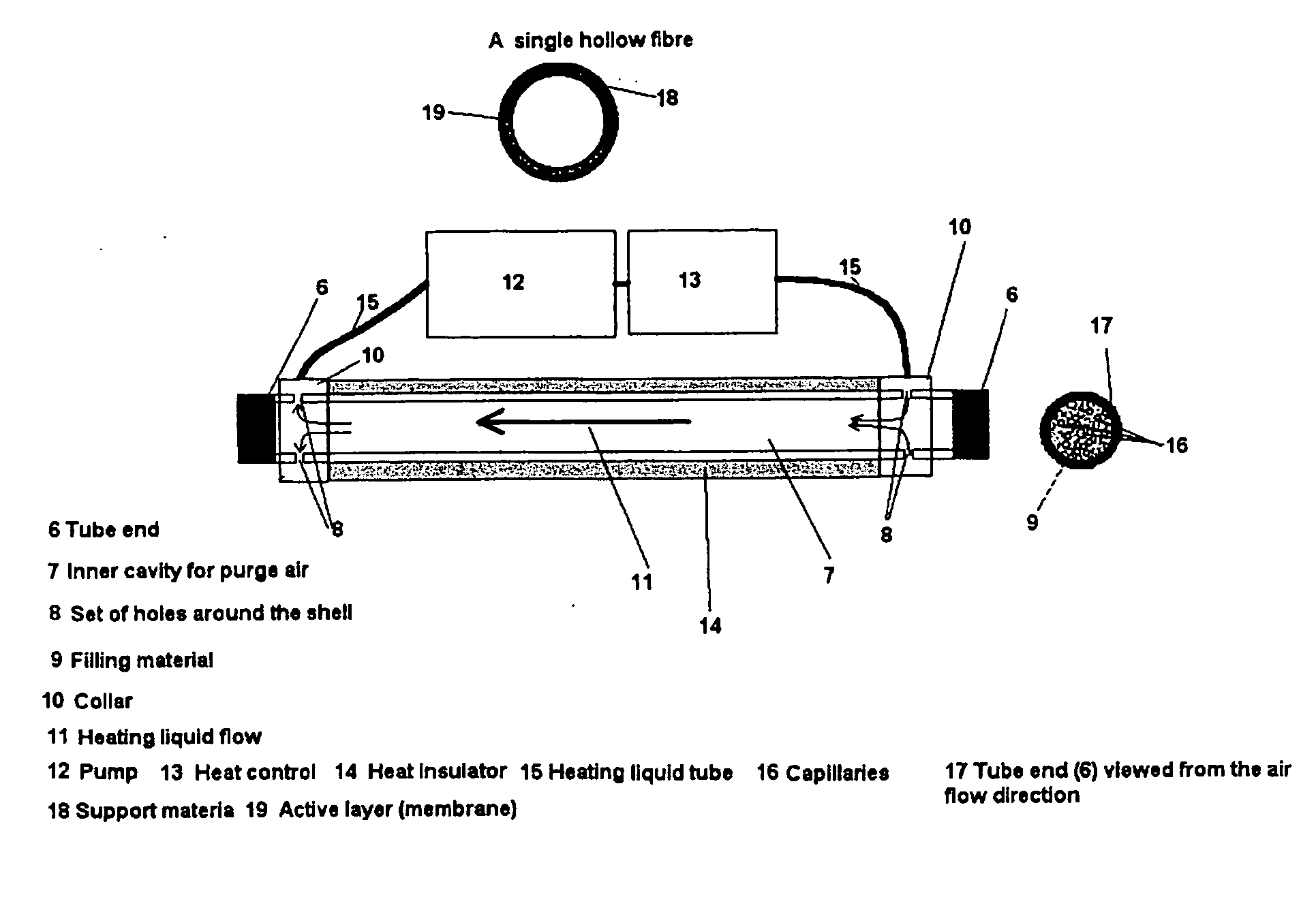
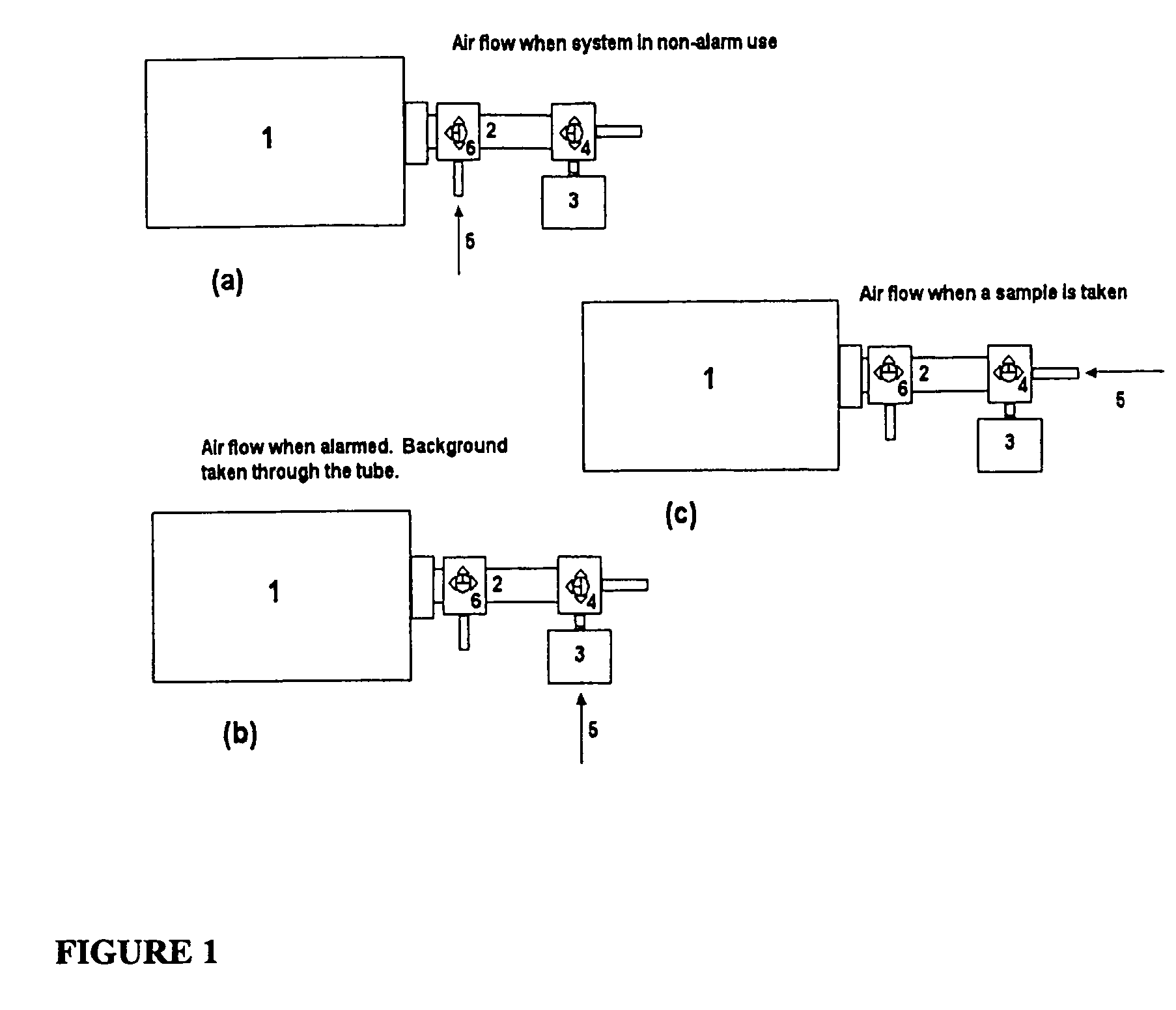
[0033]FIG. 1 describes one preferred embodiment of using the hollow fiber capillary membrane bundle (2) as a GC column combined with a chemical detector (1). The sampling arrangement contains a valve (4), a vapor adsorbing filter (3), a gas inlet (5) and an optional additional valve (6). The position of the valve (4) determines whether the sample flows through the filter (valve switched to the position 4b) or directly (valve switched to the position 4c) to the hollow fiber bundle based multicapillary GC column (2). The moment of switching the valve from position 4b to 4c determine the t=0 for retention time.

[0034] Another preferred embodiment, also shown in FIG. 1, involves the additional valve (6) which is used to control whether the hollow fiber bundle based GC column is in use (position 6b or 6c) or not (position 6a). A faster response time is possible when a hollow fiber bundle is not used (position 6a), but a more specific identification with less cross-sensitivity is possible...


PUM


Abstract

The invention relates to a gas chromatograph for the analysis of gas samples. It has a feed arrangement for feeding the sample, an open tubular capillary column for separating the components of the sample, temperature control means for controlling the temperature of the column, and a detector for detecting the separated components of the sample. The efficiency has been improved and a convenient hand-held version has been made possible by constructing the column of a bundle of open tubular capillaries having a gas permeable wall comprising a polymer membrane. The invention also relates to the use of such a column together with a detector for identifying gaseous samples.

Description

1. FIELD OF THE INVENTION [0001] The invention relates to a gas chromatograph for the analysis of a sample, having a feed arrangement for feeding the sample, an open tubular capillary column for separating the components of the sample, temperature control means for controlling the temperature of the column, and a detector for detecting the separated components of the sample, wherein said column comprises a bundle of open tubular capillaries. 2. BACKGROUND [0002] The chemical state of a gas phase sample is formed by vaporized or gaseous chemical species mixed with an ambient medium, typically environmental air. Instead of air, the medium can be process gases or vacuum. The detector is used to detect and identify defined chemical species in the defined surrounding media. [0003] Characteristic for a chemical detector is its capability to convert a chemical state to an electrical signal and transmit the signal for further processing. Typically it is aimed at performing both qualitative ...

Claims


Application Information

Patent Timeline
08 Nov 2007
Publication
US20070256474A1
IPC
G01N30/72; B01D53/02; B01D61/00; B01D63/02; G01N30/30; G01N30/60
CPC
B01D53/02; B01D61/00; B01D63/02; B01D2313/22; G01N30/6069; G01N30/6073; G01N2030/0095; G01N30/6043
Inventors
PAAKKANEN, HEIKKI; UTRIAINEN, MIKKO