Layout design support system, method, and program

Inactive Publication Date: 2007-11-08
KK TOSHIBA
View PDF7 Cites 40 Cited by
  • Summary
  • Abstract
  • Description
  • Claims
  • Application Information

AI Technical Summary

Benefits of technology

[0031] The present invention provides a layout design support system, method, and program which are capable of supporting a process for creating a detai

Problems solved by technology

In either case, the construction costs for constructing a building for housing the equipments increases in accordance with the surface are a of the equipments.
Further, route design relating to the paths taken by the pipes and cables that connect the equipments must be performed with regard to the sizes and positions of the buildings and equipments, as well as external interference relating to prepared lines for electricity, water supply and sewerage, fuel, and so on.
For example, main steam pipes which are capable of withstanding high temperatures and high-pressure, power cables which are capable of withstanding high voltages, and so on are extremely expensive, and hence when the length of the piping and cables increases, the amount of material rises, leading to cost increases.
In particular, when the distance of a cable increases, more expensive cable must be selected to prevent the effects of voltage drop, and it is therefore extremely important to reduce the cable distance.
Likewise with respect to the construction of steel structures known as piping racks and cable racks, which are used during installation of the piping and cable, and the excavation work required to lay the piping and create cable trenches, costs rise as the distance increases.
In reality, however, piping and cable are almost never designed to take the shortest route between equipments.
More specifically, when the plant is operative, a considerable amount of vibration and noise is typically generated, and hence sufficient consideration must be given to ways of preventing the vibration and noise from affecting the environment on the exterior of the site.
In addition to conditions on the design content of the layout design, many constraints are applied to layout design as an estimate operation due to the fact that layout design is positioned at the beginning of

Method used


Image

  • Layout design support system, method, and program
  • Layout design support system, method, and program
  • Layout design support system, method, and program

Examples


Embodiment Construction

[System Constitution]

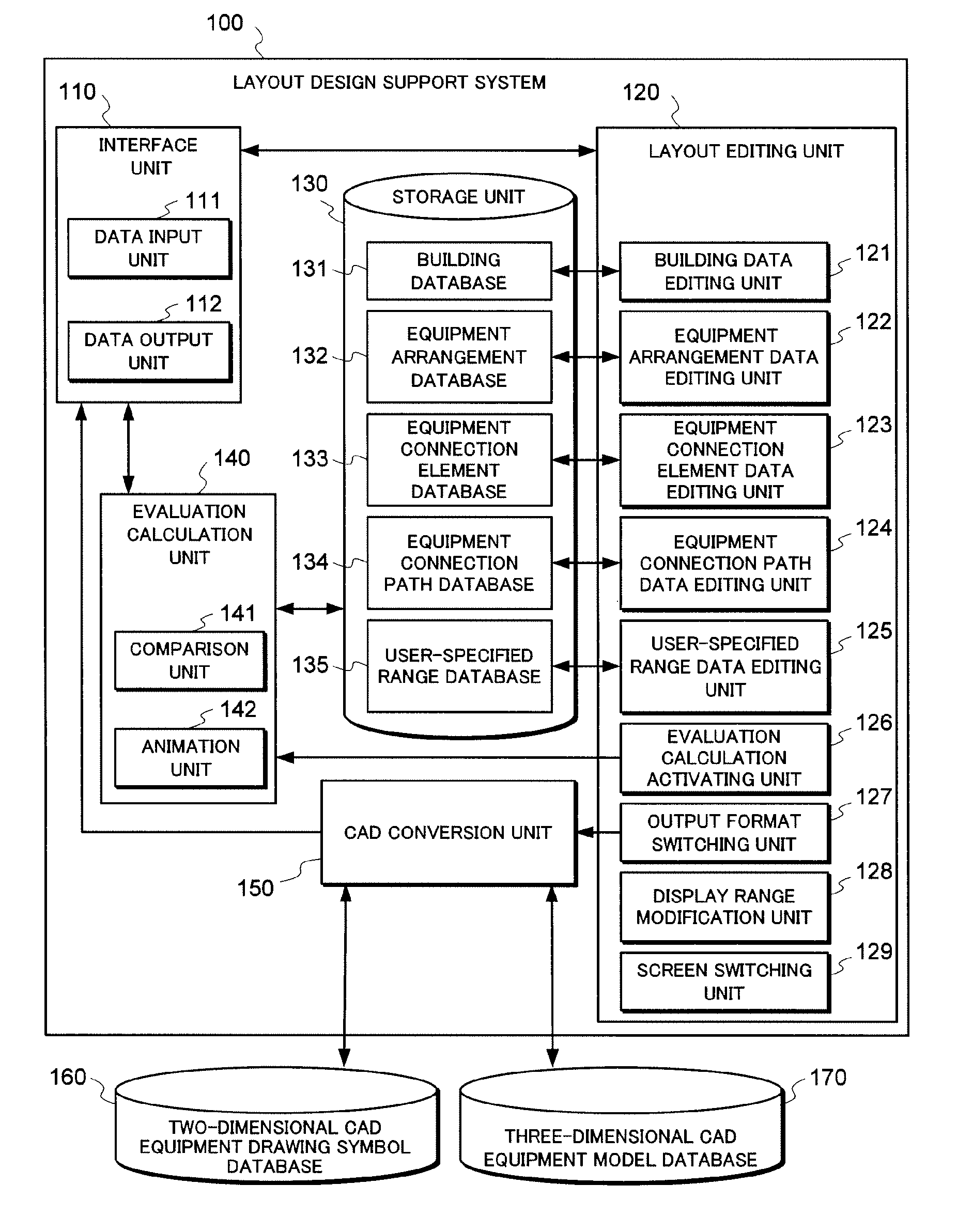
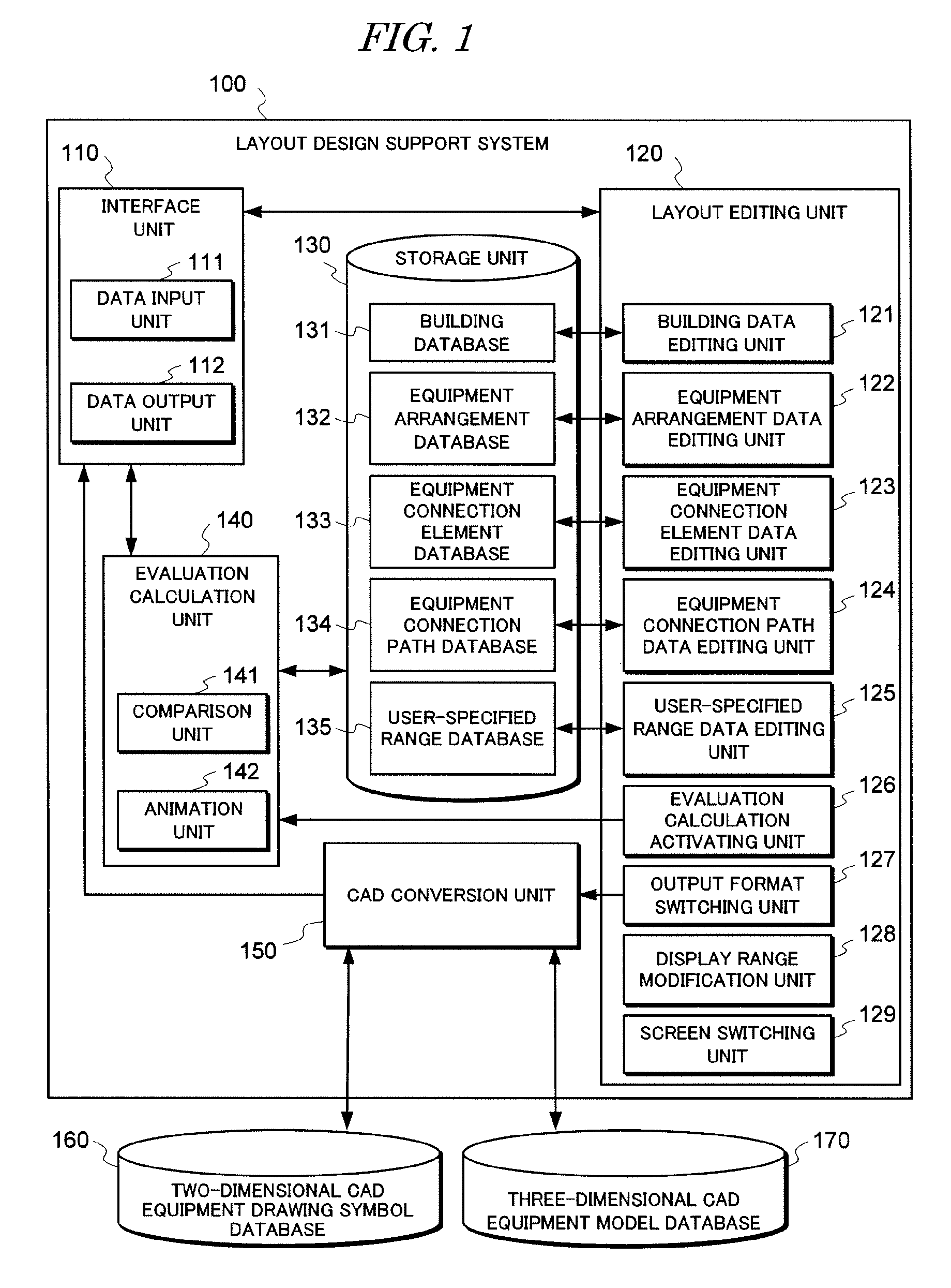
[0064]FIG. 1 is a block diagram showing an embodiment of a layout design support system to which the present invention is applied. As shown in FIG. 1, a layout design support system 100 according to this embodiment is constituted by an interface unit 110, a layout editing unit 120, a storage unit 130, an evaluation calculation unit 140, and a CAD conversion unit 150, all of which are realized on a computer. Each unit 110, 120, 130, 140, 150 will be described in detail below.

[0065] The interface unit 110 is constituted by a data input unit 111 and a data output unit 112. Here, the data input unit 111 is an input apparatus such as a mouse or keyboard for inputting various instructions and data into the computer in accordance with a user operation, and the data output unit 112 is an output apparatus such as a display or printer for displaying or outputting data input through the data input unit 111, data stored in the data storage unit 130, and results processed ...


PUM


Abstract

The present invention enables support of a process for creating a detailed layout design which takes construction into account, and contributes to a reduction in the workload of the layout design process. A layout editing unit causes an interface unit to display a layout design data editing screen, receives an edit instruction input onto the screen, and edits the layout design data in accordance with the edit instruction. The layout editing unit classifies the layout design data into five data types, namely building data, equipment arrangement data, equipment connection element data, equipment connection path data, and user-specified range data, and edits the data of each data type individually. A storage unit stores the editing results of the layout design data. A CAD conversion unit converts the layout design data into a two-dimensional CAD drawing or a three-dimensional CAD model, and causes the interface unit to display the two-dimensional CAD drawing or three-dimensional CAD model on a screen.

Description

BACKGROUND OF THE INVENTION [0001] 1. Field of the Invention [0002] The present invention relates to a technique for supporting layout design, including the arrangement of a building and a plurality of equipments within a layout range space of a plant and connections between the equipments, using a computer. [0003] 2. Description of the Related Art [0004] Layout design of various types of plant facilities, such as chemical plants and power plants for generating thermal power, nuclear power, hydropower, and so on, is performed on a plant design enterprise side when providing a price estimate or at an early stage of the design process, and encompasses concepts such as the arrangement of buildings, equipments, piping, cables, and so on, for example. This layout design process must be performed in accordance with various conditions relating to the design content and various industry-related conditions. Hereafter, these conditions will be divided broadly into “conditions for arranging ob...

Claims


Application Information

Patent Timeline
IPC IPC(8): G06F17/50
CPCG06F2217/34G06F17/5004G06F2113/14G06F30/13G06F30/392G06F9/00G06F9/06
Inventor OKADA, YUUKI
Owner KK TOSHIBA
Why Eureka
Try Eureka