Precision tool holder with flexure-adjusted, three degrees of freedom for a four-axis lathe

a tool holder and tool technology, applied in the field of machining tools, can solve the problems of large size, large accuracy of machined workpiece surface, and inability to adjust the flexure angle, etc., and achieve the effect of improving the accuracy of machined workpiece surfa

Inactive Publication Date: 2007-11-15
LAWRENCE LIVERMORE NAT SECURITY LLC
View PDF11 Cites 19 Cited by
  • Summary
  • Abstract
  • Description
  • Claims
  • Application Information

AI Technical Summary

Benefits of technology

[0017] Generally, the present invention relates to a tool holder capable of precisely positioning a single point diamond tool on the B-axis of a four-axis diamond turning machine or lathe. In particular, the tool holder is designed to adjust the cutting tool position in three orthogonal directions with sub-micron resolution, e.g. up to 20 nm resolution using flexure-based adjustment mechanisms to move the cutting tool. In particular, flexure hinges are used which enable and guide movement of a platform of lever arm in only one of the ijk directions with minimal parasitic error. As such, the tool holder does not contain any mechanical components with surfaces that slide relative to each other, so there is no potential for trapped friction to be released and cause unintended movement of the cutting tool. Also, the cross-talk between axes when making flexure-based adjustments is minimal and insignificant, with parasitic error motion typically less than 0.1 μm, so it enables tools to be set relatively rapidly to machine complex components with sub-tem accuracy. And making an adjustment to the tool position requires the user to simply turn a manual micrometer adjuster, which is much simpler than the process required for previously designed tool holders.

Problems solved by technology

The accuracy of a machined workpiece surface, however, is generally limited by the accuracy with which the tool is set in place.
This tool holder, however, is a complicated design that requires a control system to drive the piezo actuators and is considered too large in size for modem commercial diamond turning machines.
Such sliding-plate tool holders, however, can exhibit cross-talk, i.e. where tool adjustment in one of the i and j directions can cause movement by more than 1 μm in each of the other orthogonal directions, which complicates setting the tool with sub-em accuracy in all the i, j, and k directions simultaneously.
For example, depending on the circumstances and the required level of accuracy, setting the tool correctly can take a skilled operator up to 16 hours.
In addition, each time the tool is adjusted friction becomes trapped in the sliding components of the tool holder.
If proper measures are not exercised this trapped friction can be released in the form of incremental slipping of the sliding plates.
This slipping can cause the tool to move several μm over the course of a few days, which further complicates the issue of keeping the tool centered correctly on the B-axis.
Therefore, when machining precision components, a significant portion of the machinist's time is typically spent setting, resetting, and checking the tool position.
As such, such sliding-plate tool holders have limited accuracy and cannot position the tool with the precision required for machining complex high-precision parts and components, such as for example high-precision meso-scale laser targets.
It is notable that even if one of the ijk directions (such as the k height direction) did not involve sliding plate actuation, but was rather based on a flexure-based actuator mechanism, the set of sliding plates used for adjustment in the i and j directions would make the adjustment precision in those sliding directions on the order of several microns, which is not suitable for precision machining of complex meso-scale components with sub-μm profile requirements.
However, in contrast to workpieces that are large enough and stable enough to be measured accurately with the LVDT, such error compensation techniques are difficult to apply to meso-scale components with complex three-dimensional shapes, such as components for laser targets, since these components often contain both interior and exterior features or they are too complex or too fragile to be reliably measured.
However, many commercially available four-axis diamond turning machines do not currently have the capability to allow programming in a virtual, tool-centered coordinate system.

Method used


Image

  • Precision tool holder with flexure-adjusted, three degrees of freedom for a four-axis lathe
  • Precision tool holder with flexure-adjusted, three degrees of freedom for a four-axis lathe
  • Precision tool holder with flexure-adjusted, three degrees of freedom for a four-axis lathe

Examples


Embodiment Construction

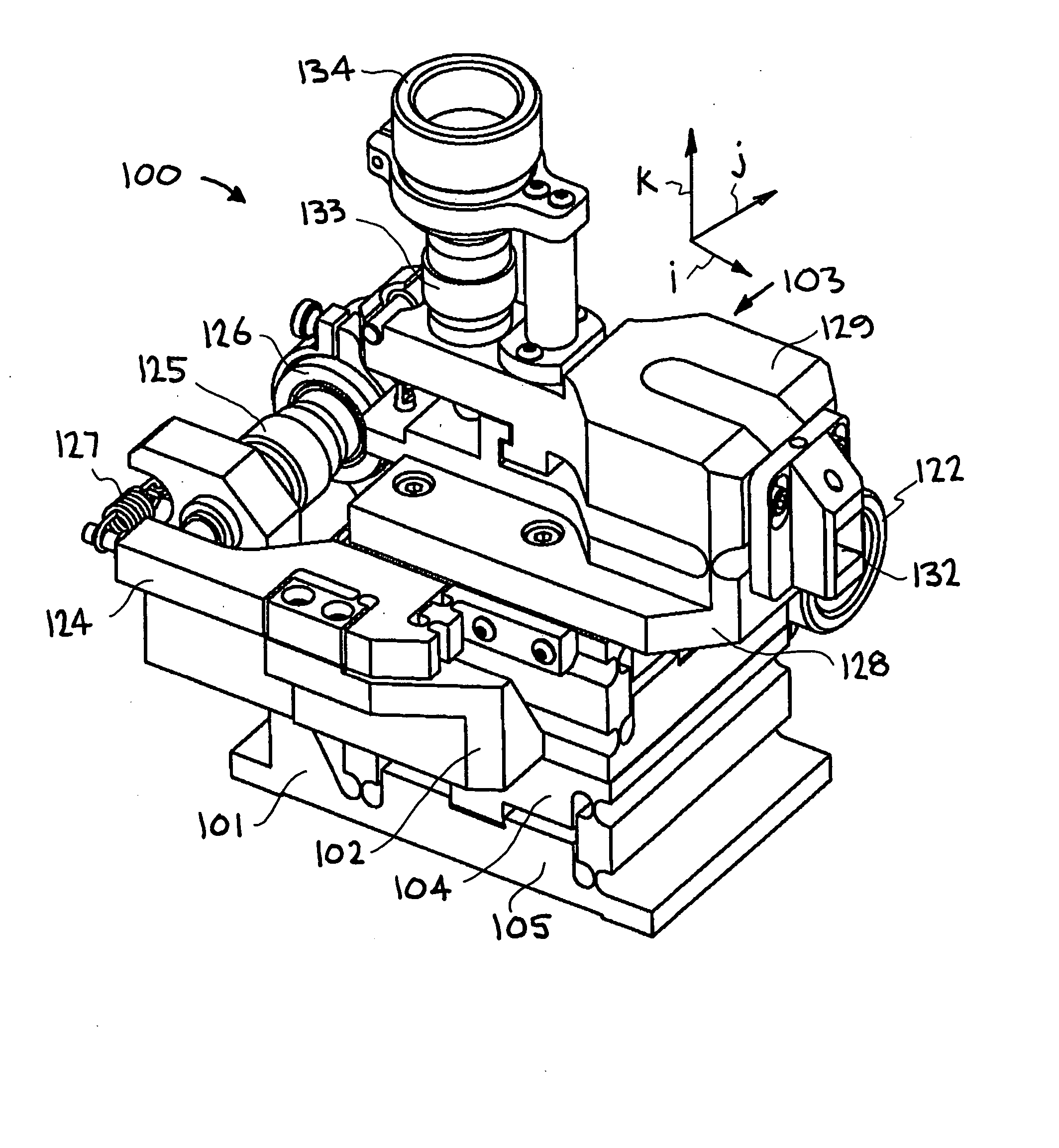
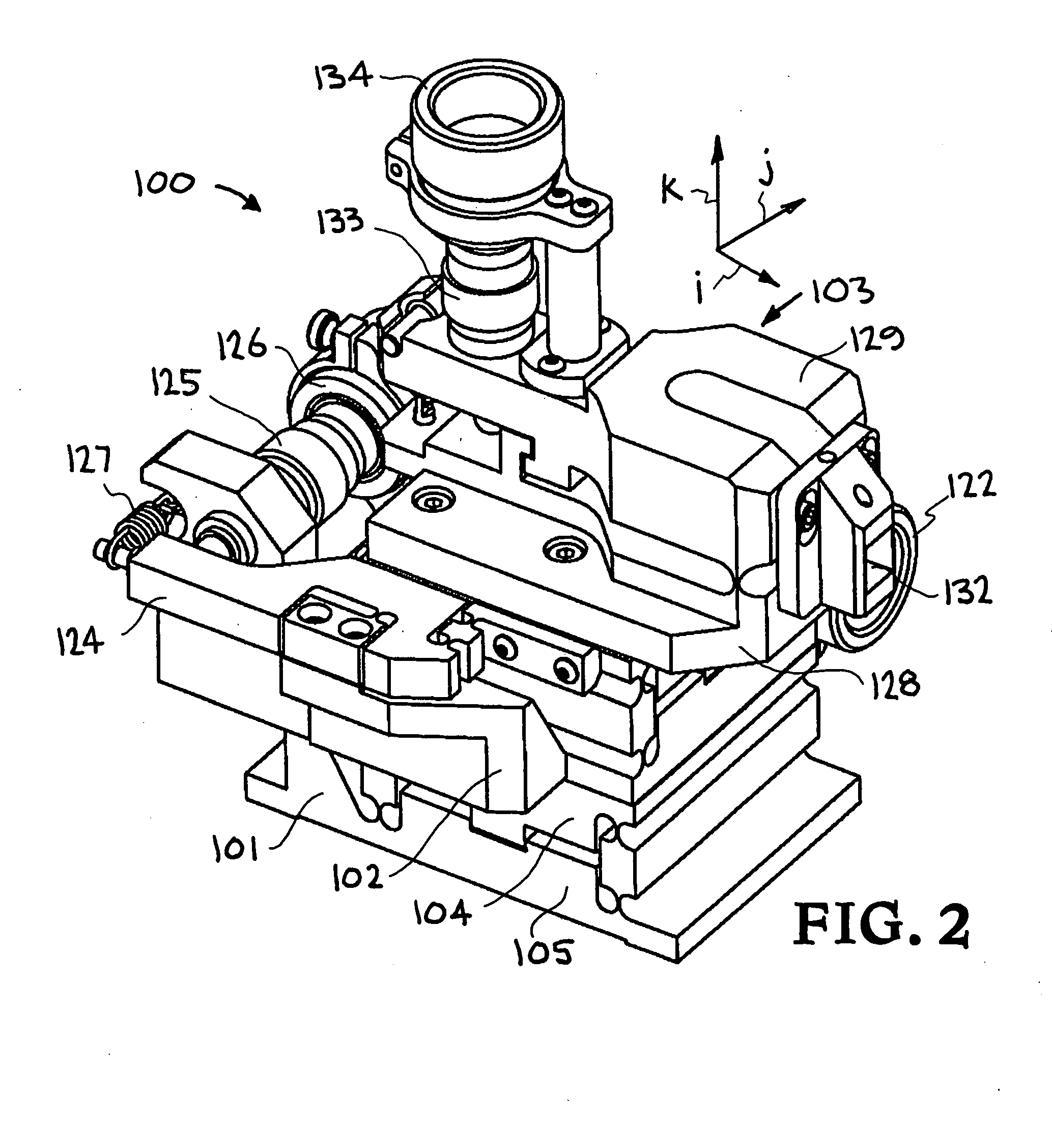
[0029] Turning now to the drawings, FIGS. 2 and 3 show isometric front and back views of an exemplary embodiment of the precision tool holder of the present invention, generally indicated at reference character 100, which facilitates the machining of precision meso-scale components with complex three-dimensional shapes with sub-μm accuracy on a four-axis lathe. Generally, the tool holder 100 includes three independently operable flexure-based adjustment mechanisms, indicated at 101-103, that allow adjustment of a tool in the three ijk orthogonal directions. The adjustment mechanism are stacked together to form three tiers or levels, with a first adjustment mechanism 101 shown at the bottom, a second adjustment mechanism 102 shown in the middle, and a third flexure-based adjustment mechanism 103 shown at the top. The first adjustment mechanism 101 is mountable directly on a rotary table (not shown).

[0030] Each of the three adjustment mechanisms 101-103 include a flexure assembly com...


PUM

PropertyMeasurementUnit
Degrees of Freedomaaaaaaaaaa
displacementaaaaaaaaaa
tensile yield strengthaaaaaaaaaa

Abstract

A precision tool holder for precisely positioning a single point cutting tool on 4-axis lathe, such that the center of the radius of the tool nose is aligned with the B-axis of the machine tool, so as to facilitate the machining of precision meso-scale components with complex three-dimensional shapes with sub-μm accuracy on a four-axis lathe. The device is designed to fit on a commercial diamond turning machine and can adjust the cutting tool position in three orthogonal directions with sub-micrometer resolution. In particular, the tool holder adjusts the tool position using three flexure-based mechanisms, with two flexure mechanisms adjusting the lateral position of the tool to align the tool with the B-axis, and a third flexure mechanism adjusting the height of the tool. Preferably, the flexures are driven by manual micrometer adjusters. In this manner, this tool holder simplifies the process of setting a tool with sub-μm accuracy, to substantially reduce the time required to set the tool.

Description

I. CLAIM OF PRIORITY IN PROVISIONAL APPLICATION [0001] This application claims priority in provisional application No. 60 / 758,729, filed on Jan. 12, 2006, entitled “Precision Tool Holder with Three Degrees of Freedom for a 4-axis Lathe” by Matthew J. Bono et al.II. STATEMENT OF FEDERALLY SPONSORED DEVELOPMENT [0002] The United States Government has rights in this invention pursuant to Contract No. W-7405-ENG-48 between the United States Department of Energy and the University of California for the operation of Lawrence Livermore National Laboratory.III. BACKGROUND OF THE INVENTION [0003] A. Technical Field [0004] This invention relates to machining tools. In particular, the invention relates to a precision tool holder designed to enable the machining of precision meso-scale components with complex three-dimensional shapes with sub-micron accuracy on a four-axis lathe. [0005] B. Description Of The Related Art [0006] Cutting parts on a lathe is one of the oldest and most versatile mac...

Claims


Application Information

Patent Timeline
Patent Type & Authority Applications(United States)
IPC IPC(8): B23B29/04
CPCB23B29/04B23B2226/31B23B2260/0045B23Q1/34Y10T82/2512B23Q2210/002Y10T82/2585Y10T82/2583B23Q3/18
Inventor BONO, MATTHEW J.HIBBARD, ROBIN L.
Owner LAWRENCE LIVERMORE NAT SECURITY LLC
Why Eureka
Try Eureka