High pressure turbine airfoil recovery device and method of heat treatment

a high-pressure turbine and recovery device technology, applied in heat treatment equipment, furnaces, manufacturing tools, etc., can solve the problems of high operating stress, inability to recover metallurgical damage, and high operating stress, and achieve the effect of maximizing the energy withdrawn from hot gas, restoring fatigue and creep-rupture properties of blades, and reducing leakage of hot corrosiv

Inactive Publication Date: 2007-11-22
GENERAL ELECTRIC CO
View PDF19 Cites 23 Cited by
  • Summary
  • Abstract
  • Description
  • Claims
  • Application Information

AI Technical Summary

Benefits of technology

[0015]A turbine blade used in a gas turbine engine comprises an airfoil portion extending outward into the hot gas flow path of the turbine engine, a dovetail portion that attaches the turbine blade to a turbine disk and a platform portion that is intermediate the airfoil portion and the dovetail portion. A shank portion provides a transition between the platform portion and the dovetail portion, the shank portion and the dovetail portion comprising the blade below the platform portion. The airfoil portion of the turbine blade is of a thin, curvilinear design engineered to allow for smooth fluid flow of gas over the airfoil portion surface in the engine gas flow path, while maximizing the energy withdrawn from the hot gas. The gas contacting an flowing over the airfoil portion powers the turbine. A plurality of turbine blades are attached to the turbine disk. While the platform is an optional feature in a blade, the platform is oriented substantially perpendicular to the dovetail portion and the airfoil portion. The platform assists in reducing the leakage of hot corrosive, oxidative combustion gases below the platform and between the blade dovetail portion and the mating disk dovetail slots, thereby providing protection to both the disk and the blade dovetail portion from the hot corrosive / oxidative combustion gases.
[0016]The present invention accomplishes restoration of the metallurgical structure of the airfoil portion of the turbine blade to that which approximates the microstructure of a new-make blade, typically an as-cast microstructure, without disturbing the microstructure of the blade below the blade platform, thereby restoring the fatigue and creep-rupture properties to the blade, as well as other mechanical properties. The article and method of the present invention permits restoration of blades removed from service that have deteriorated mechanical properties resulting from rafting, as well as blades that have been weld repaired to restore damaged portions of the airfoil portion. The weld repair may be accomplished by any traditional weld repair method, such as SWET welding, TIG welding laser welding or any other well-known welding repair method to restore the airfoil portion of damaged new-make blades or blades removed from service. The blade undergoing metallurgical restoration, as discussed above, experiences rafting in the airfoil portion either as a result of in-service operation or as a result of weld repair, or both. In order to restore the microstructure of the blade to new-make conditions, typically an as-cast microstructure, rafting is eliminated from the airfoil portion by heating only the airfoil portion above the solutioning temperature, thereby resolutionizing it. The airfoil portion can then be precipitation-hardened to provide a preselected microstructure compatible with its intended future use.

Problems solved by technology

Thus the blades operate in an oxidative and corrosive environment, and are subjected to high operating stresses.
In order to survive these harsh conditions, the turbine blades are made from superalloys, an expensive blend of elements that provide oxidation resistance, corrosion resistance and strength.
The turbine blades nevertheless are subject to damage as a result of operation in the gas turbine engine.
The metallurgical damage is inherent as a result of normal operation of the gas turbine engine.
However, operation of the blades at the high temperatures of the turbine engine for extended periods of time results in fatigue, creep-rupture and rafting.
The problem with welding of blades is that the weld area and heat affected zone (the “HAZ”) are heated above the solutioning temperature of the gamma prime.
As heat is transferred away from the repair area, and in portions of the HAZ, the temperature of the metal is increased, but not to a temperature sufficient to raise the alloy above the solutioning temperature of the γ′.
Thus, mechanical repair by welding does not provide a solution to the metallurgical problems related to extended use of precipitation-hardened alloys at elevated temperatures, and in certain cases, may further exacerbate the problem.
Although the prior art discloses that the weld area is desirably stress relieved and rapidly cooled to a temperature below the γ′ precipitation hardening temperature, the prior art does not address the problem of rafting in other regions of the airfoil portion of the blade that may be distal weld repair.
The prior art does not recognize the need to restore the metallurgical properties of airfoils not subject to weld repair.
No post-sintering heat treatments are discussed; however the patent does disclose coarsening of the gamma prime near the blade tip that was judged to be acceptable, but does not recognize the problem of continued coarsening of this gamma prime that will inevitably result from high temperature exposures for long periods of time.
Of course, obvious methods of heating may be substituted for the radiant heat source, such as for example, induction coils, but such substitutions do not provide recognition of the problem of continued coarsening, or alleviation of coarsening that has already occurred.
This process is effective in providing uniform γ′ in the airfoil portion of the blade, but presents other problems.
These operations result in residual stresses.
Thus. a high temperature solutioning treatment of those portions of the blade below the platform is undesirable as it can result in recrystallization of these portions due to the residual stresses.
Since many modern blades are either directionally solidified (providing large columnar grains oriented parallel to the longitudinal axis of the blade) or are solidified as single crystals, recrystallization in this region is undesirable as it reduces strength of the blade in this region, which can be a limiting factor for the mechanical properties of the entire blade.

Method used


Image

  • High pressure turbine airfoil recovery device and method of heat treatment
  • High pressure turbine airfoil recovery device and method of heat treatment
  • High pressure turbine airfoil recovery device and method of heat treatment

Examples


Embodiment Construction

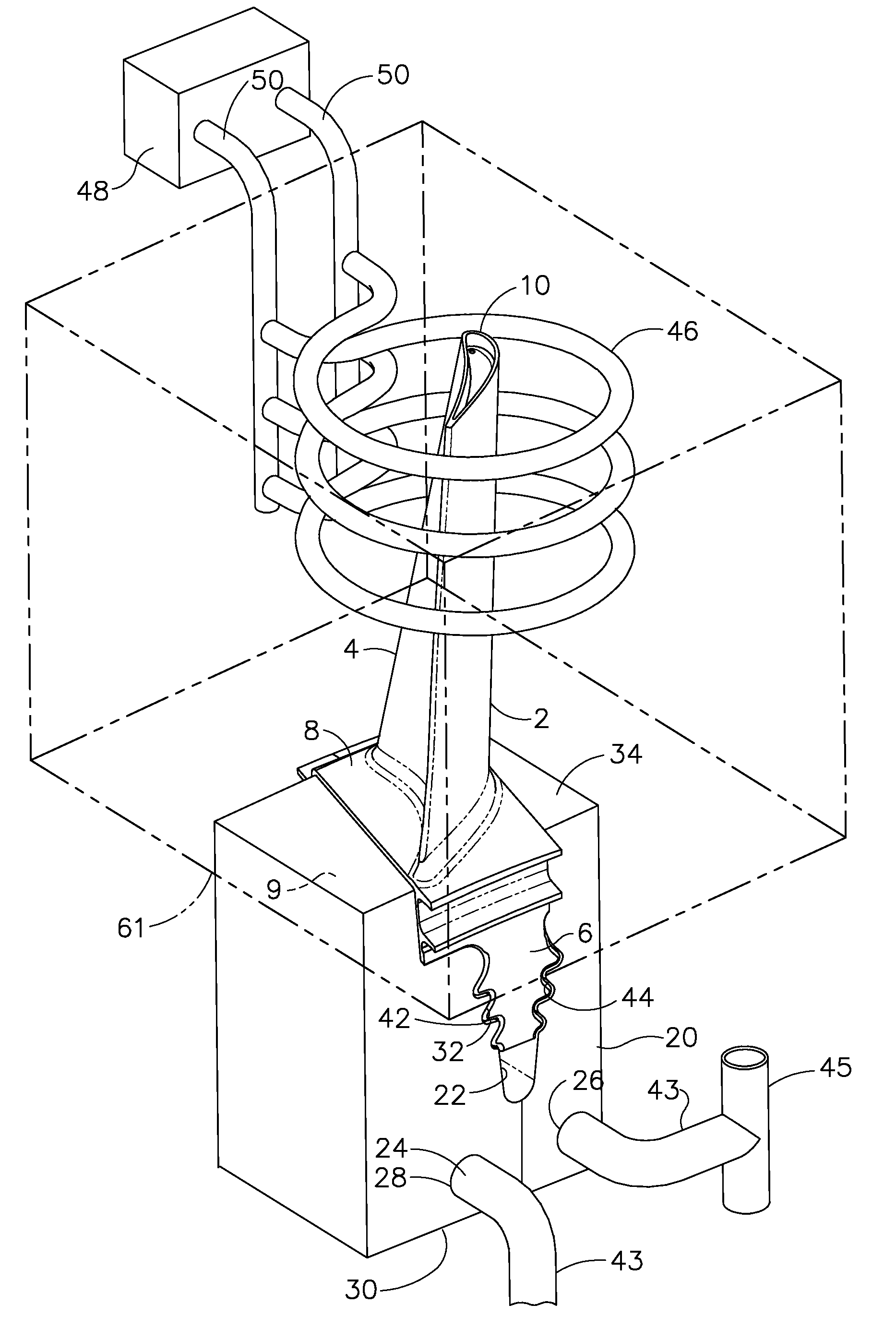
[0026]The present invention provides a method for solutioning the airfoil portion of a turbine blade and then uniformly age hardening the airfoil portion of the turbine blade without recrystallizing the portion of the turbine blade below the platform. This restoration is required once the microstructure of the airfoil portion has been modified. This solutioning and age hardening treatment of the airfoil portion of the turbine blade restores mechanical properties uniformly to the airfoil portion of the blade, while restoring a substantially uniform microstructure. The present invention further provides apparatus in the form of a fixture for accomplishing the solutioning and subsequent age hardening of the airfoil portion of the turbine blade.

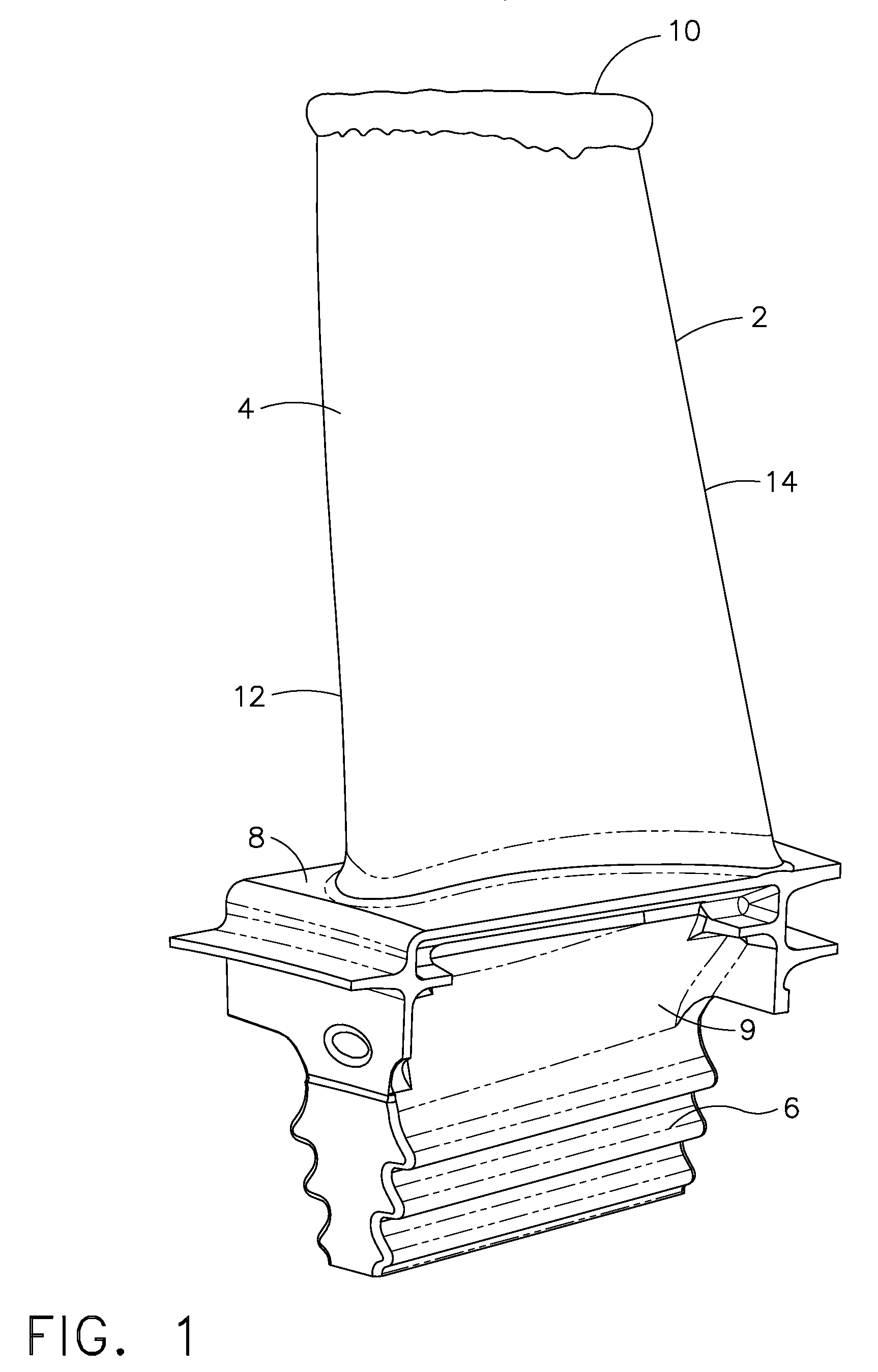
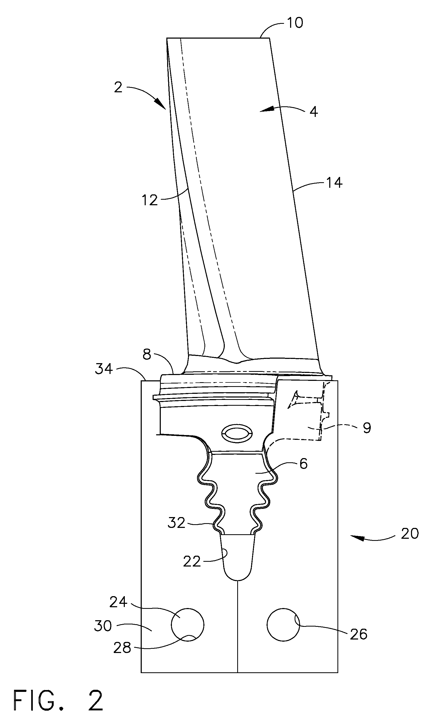
[0027]A typical turbine blade 2 is depicted in FIG. 1. However, the invention is not limited to a turbine blade, and may include other configurations having a thin section and a thick section wherein the microstructure of one section must be modi...


PUM

PropertyMeasurementUnit
temperatureaaaaaaaaaa

Abstract

A fixture and method for repairing superalloy articles. The fixture ideally holds the article in place if repairs are made. An interface between the fixture and the article facilitate transfer of heat between the article and the fixture so that the article can be differentially heat treated. A portion of the article extends from the fixture. This portion of the article, which may be repaired within the fixture or may be repaired elsewhere, is solution heat treated while in the fixture so that the area extending from the fixture is solutioned, while heat is transferred from the article through the fixture, thereby preventing the temperature of the portion of the article within the fixture from being elevated so as to modify its microstructure. The solutioned portion can then be heat treated, while in the fixture, to precipitation harden it as desired.

Description

FIELD OF THE INVENTION[0001]The present invention is directed to an apparatus for fixturing an airfoil and to a method for solutioning a portion of the airfoil followed by aging the solutioned airfoilBACKGROUND OF THE INVENTION[0002]An aircraft gas turbine engine or jet engine draws in and compresses air with an axial flow compressor, mixes the compressed air with fuel, burns the mixture, and expels the combustion product through an axial flow turbine section that powers the compressor. The turbine section of the engine includes one or more disks, each disk including a plurality of blades projecting from its periphery. The hot exhaust gases strike the blades causing the disk(s) to rotate. The rotating disk(s) are attached to a shaft that also drives a compressor. The compressor is also made from rotating disks, each disk having a plurality of blades projecting from its periphery. The disk turns rapidly on a shaft as the shaft is rotated by the turbine, and the curved blades draw in ...

Claims


Application Information

Patent Timeline
Patent Type & Authority Applications(United States)
IPC IPC(8): C22C19/05C22F1/10
CPCB23P6/007C21D9/0068C22F1/10F05D2230/80Y02T50/67F05D2230/40F01D5/005Y02T50/60
Inventor KELLY, THOMAS J.GROSSKLAUS, WARREN D.THOLKE, BRENT R.GOVERN WALSTON, CHRISTINE
Owner GENERAL ELECTRIC CO
Why Eureka
Try Eureka