Apparatus for detecting magnetic signals and signals of electric tunneling

a technology of electric tunneling and apparatus, applied in the field of apparatus for detecting magnetic signals and signals of electric tunneling, can solve the problems of mrfm not being able to detect the magnetic field generated by current, the application of this instrument is limited, and the requirement of a cryogenic environment and modest spatial resolution, so as to improve the efficiency of flux coupling, improve the spatial resolution of the apparatus, and improve the effect of spatial resolution

Inactive Publication Date: 2007-11-22
NATIONAL TSING HUA UNIVERSITY
View PDF4 Cites 12 Cited by
  • Summary
  • Abstract
  • Description
  • Claims
  • Application Information

AI Technical Summary

Benefits of technology

[0010] To enhance the spatial resolution of an apparatus detecting magnetic signals, a high-permeability tip is disposed to sense the magnetic field generated by sample. The spatial resolution is thus determined by the diameter of vertex of the tip. In consideration of without influencing the magnetic state of sample, the high-permeability tip should have a residual moment and a coercive force as small as possible. Using the technology of microelectromechanical systems (MEMS) can sharpen the tip with a high aspect ratio to a diameter around 10 nm. A pick-up coil inductively coupling with the thick stem of the tip transfers the magnetic flux to a magnetic sensitive device measuring the magnetic signals. There is no restriction in the position of the magnetic sensitive device in this arrangement. In consideration of impedances matching, a transformer can be designed to reconcile the difference between the pick-up coil and the magnetic sensitive device. The employment of superconducting pick-up coil and transformer can further improve the flux coupling efficiency. In the present invention, the magnetic sensitive device is a device sensitive to magnetic field, magnetic flux and magnetic force. There are several variations in the magnetic sensitive device, which comprise at least a magnetic sensor such as Hall sensor, giant magnetoresistance (GMR) device, tunnel magnetoresistance (TMR) device and SQUID. The preferred magnetic sensor is SQUID. In order to suppress the magnetic noise, a magnetic shield comprising such as u-metal or superconductor is applied to cover the pick-up coil and the high-permeability tip except the apex. Several slits on the shield in parallel with the axis of the tip are constructed to reduce the interference of eddy currents or induced supercurrents. Typically an SPM has a module of actuation control for the function of scanning. The module of the electric and actuated control in the present invention is for this purpose. In this sense, the apparatus described here is an SPM capable of detecting magnetic signal with improved spatial resolution. More specifically the apparatus just described is a SSM with an improved spatial resolution.
[0011] In the case of high-permeability metallic tip, the apparatus described in this invention is capable of detecting signals of electric tunneling and magnetic signals simultaneously. The module of electric and actuated control monitors the tunneling currents and controls the separation between the tip and sample in the way well known to a person skilled in the art of STM. Operating in the mode of constant tunneling current usually allows the separation between the tip and sample stably keep in the order of magnitude of angstrom. This can enhance the accuracy and the sensitivity of magnetic signal further.
[0012] The application of the present invention is not limited to an SPM. A module of coupling magnetic signals to a magnetic sensitive device, comprising a tip, a magnetic sensitive device, a coil transferring the magnetic flux of the tip to the magnetic sensitive device and a magnetic shield etc., can be applied to an apparatus of detecting magnetic signal. The respective components of this module are similar to that described previously. This module can enable an apparatus to have more degrees of freedom to dispose the magnetic sensitive device and to enhance spatial resolution without losing magnetic sensitivity.
[0013] Unlike the U.S. Pat. No. 6,211,673 B1 that the magnetic-field device is restricted to be disposed on an AFM cantilever, this invention provides a new method to couple the magnetic flux. This method has several benefits than the previous one, which are an enhanced flux coupling that can be achieved by increasing the winding turns of the coil, by winding coils directly on the other end of the tip or the magnetic-flux guide, and a flexible site to place the SQUID chip. These two advantages can significantly improve the performance in scanning magnetic signal. For example, the enhanced flux coupling can increase the magnetic sensitivity and the flexibility to place the SQUID chip allows people to operate the chip with the less trade-off. In the case of metallic tip, this tip has the capability of STM tip as well. Therefore, this invention can fulfill the function of detecting delicate electronic and magnetic signal in a single instrument.

Problems solved by technology

Although this technique may have the atomic-scale resolution, the application of this instrument is limited in the detection of magnetization with the imbalance of Fermi level.
The advantage of SSM is its high magnetic flux (magnetic field integrated over the sensing area) sensitivity in the range of 10−4˜10−6φ0 Hz−1 / 2 , and its disadvantage is the requirement of a cryogenic environment and modest spatial resolution.
Owing to the requirement of spin precession, MRFM cannot be used to detect the magnetic field generated by current.
The magnetic flux sensitivity of a low temperature SQUID is typically better than 10−6φ0 Hz−1 / 2 , but poor coupling efficiency of magnetic flux may degrade the sensitivity of SSM by more than one order of magnitude.
Unfortunately, the resolvable spatial feature size is proportional to the loop size.
How to keep the magnetic sensitivity and to improve the spatial resolution at the same time is a challenge.
To achieve an instrument with both of high magnetic sensitivity and high spatial resolution is still a demanding task.
SP-STM and MRFM seem like good solutions, but their application is limited in detecting the magnetic signal generated by spins.
SSM do not have this limitation however until now it is hard to solve the dilemma of magnetic sensitivity and spatial resolution.
Though U.S. Pat. No. 6,211,673 B1 proposed a possible way to tackle the problem, the arrangement of related devices is a bit of impracticability.

Method used


Image

  • Apparatus for detecting magnetic signals and signals of electric tunneling
  • Apparatus for detecting magnetic signals and signals of electric tunneling
  • Apparatus for detecting magnetic signals and signals of electric tunneling

Examples


Embodiment Construction

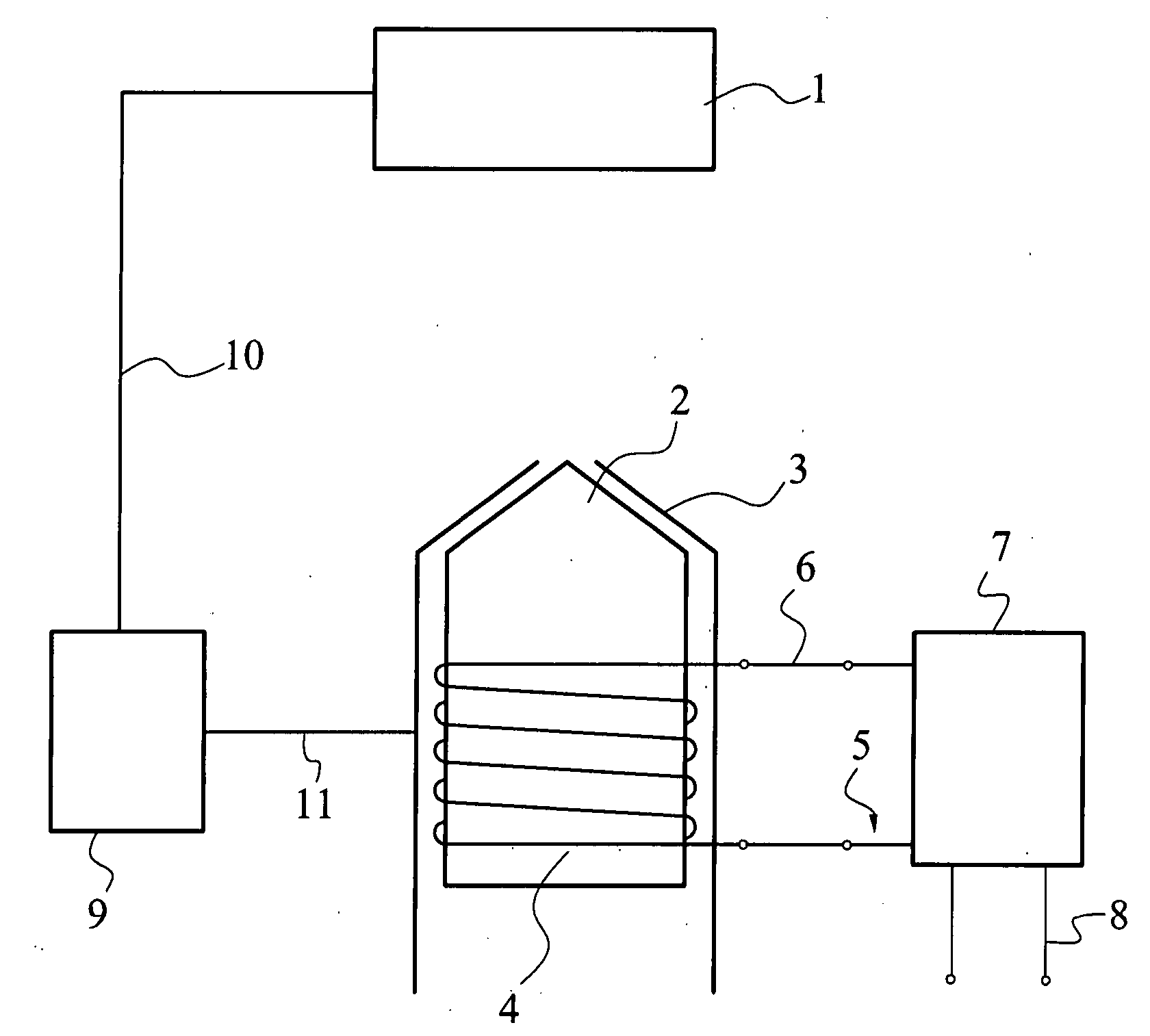
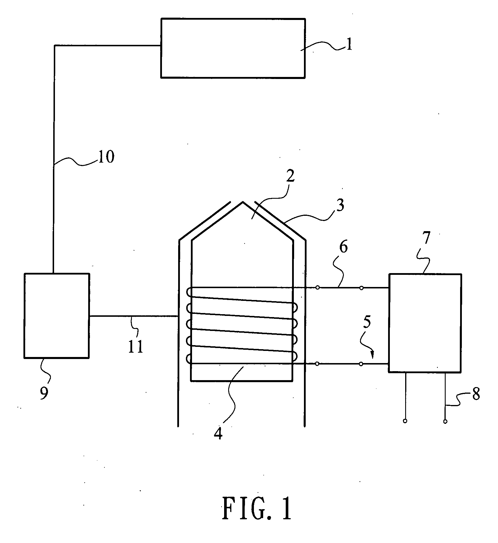
[0017]FIG. 1 schematically illustrates the embodiment of the present invention. A high-permeability material with tiny residual moment is used to fabricate the tip 2. The preferred material is Permalloy or u-metal that are the alloy of Nicole, Iron and some other transition metals. Their bulk permeability has a typical value larger than 104. The magnetic field from sample 1 induces magnetization in the tip 2. The large permeability of the tip 2 can magnify the magnetic signal. In order to reduce the magnetic noise and increase the spatial resolution, the magnetic shield 3 covers the tip 2 and the pick-up coil 4 except the very apex of the tip. The shield can be made of a high-permeability material or a superconductor. There are several slits formed on the shield to suppress eddy currents or supercurrents. Through the pick-up coil 4 inductively coupled to the tip 2 or directly wound on the tip, the magnetic signal is transferred to the magnetic sensitive device 7 in the form of magne...


PUM


Abstract

A scanning probe microscope comprises a magnetic sensor and a sensor of electric tunneling current. The miscroscope integrates both the advantages of scanning SQUID microscope (SSM), and scanning tunneling microscope (STM), into a single instrument by applying a high-permeability metallic tip such as a permalloy tip, a pick-up coil and a transformer coupling the tip and the SQUID chip together. The local magnetic field of the test sample induces a substantial magnetization in the probing tip of high permeability. Through the pick-up coil inductively coupled to the tip, the magnetic signal of the induced moment is transferred to the SQUID chip via the transformer to achieve the best flux transferring condition. The metallic tip has the capability of sensing tunneling current and thus this instrument can also retain the capabilities of the STM, such as topography, current images and mappings of local density of state. This microscope can be used to observe both the magnetic signal and the electric tunneling signal simultaneously and can manipulate the tip by using either the magnetic signal or the electric tunneling signal as the feedback control.

Description

BACKGROUND OF THE INVENTION [0001] 1. Field of the Invention [0002] The present invention relates to an apparatus for building up a scanning probe microscope with the capability of detecting delicate electronic and magnetic signal. It combines the advantages of two microscopes—Scanning SQUID Microscope (SSM) and Scanning Tunneling Microscope (STM). The SSM is capable of measuring a delicate variation of magnetic field, and the STM can resolve tunneling currents in atomic scale. [0003] 2. Description of the Prior Art [0004] The current technology of scanning probe microscope (SPM), which can observe phenomena in micro world through scanning probe tip over sample, is developed from scanning tunneling microscope (STM) first disclosed in Phys. Rev. Lett. 49, 57 (1982) by G. Binnig et al. The main components of STM are tunneling tip, scanning module for controlling the relative position between tip and sample, and detecting and processing module for measuring the related electric signal ...

Claims


Application Information

Patent Timeline
Patent Type & Authority Applications(United States)
IPC IPC(8): G01R33/02
CPCG01R33/02G01R33/0354G01R33/10G01Q60/54G01Q60/02G01Q60/16B82Y35/00
Inventor CHI, CHENG-CHUNGLIAO, YANG-CHUNGWANG, MING-JYE
Owner NATIONAL TSING HUA UNIVERSITY
Why Eureka
Try Eureka