Method and Apparatus for Reducing the Infrared and Radar Signature of a Vehicle

a technology of infrared and radar signature, which is applied in the direction of vehicle seats, aircraft stabilisation, silicon compounds, etc., can solve the problems of reducing the performance and the range of aircraft, affecting the aerodynamics of aircraft, and high likelihood of being targeted, so as to reduce the radar signature of aircraft, reduce the structural integrity of honeycomb structure, and reduce the radar/microwave and thermal/infrared signature of a vehicle

a technology of infrared and radar signature, which is applied in the direction of vehicle seats, aircraft stabilisation, silicon compounds, etc., can solve the problems of reducing the performance and the range of aircraft, affecting the aerodynamics of aircraft, and high likelihood of being targeted, so as to reduce the radar signature of aircraft, reduce the structural integrity of honeycomb structure, and reduce the radar/microwave and thermal/infrared signature of a vehicle

US20070268173A1Active Publication Date: 2007-11-22TEXTRON INNOVATIONS

Image

  • Method and Apparatus for Reducing the Infrared and Radar Signature of a Vehicle
  • Method and Apparatus for Reducing the Infrared and Radar Signature of a Vehicle
  • Method and Apparatus for Reducing the Infrared and Radar Signature of a Vehicle

Examples


Embodiment Construction

[0020] While the making and using of various embodiments of the present invention are discussed in detail below, it should be appreciated that the present invention provides many applicable inventive concepts, which can be embodied in a wide variety of specific contexts. The specific embodiments discussed herein are merely illustrative of specific ways to make and use the invention and do not delimit the scope of the invention.

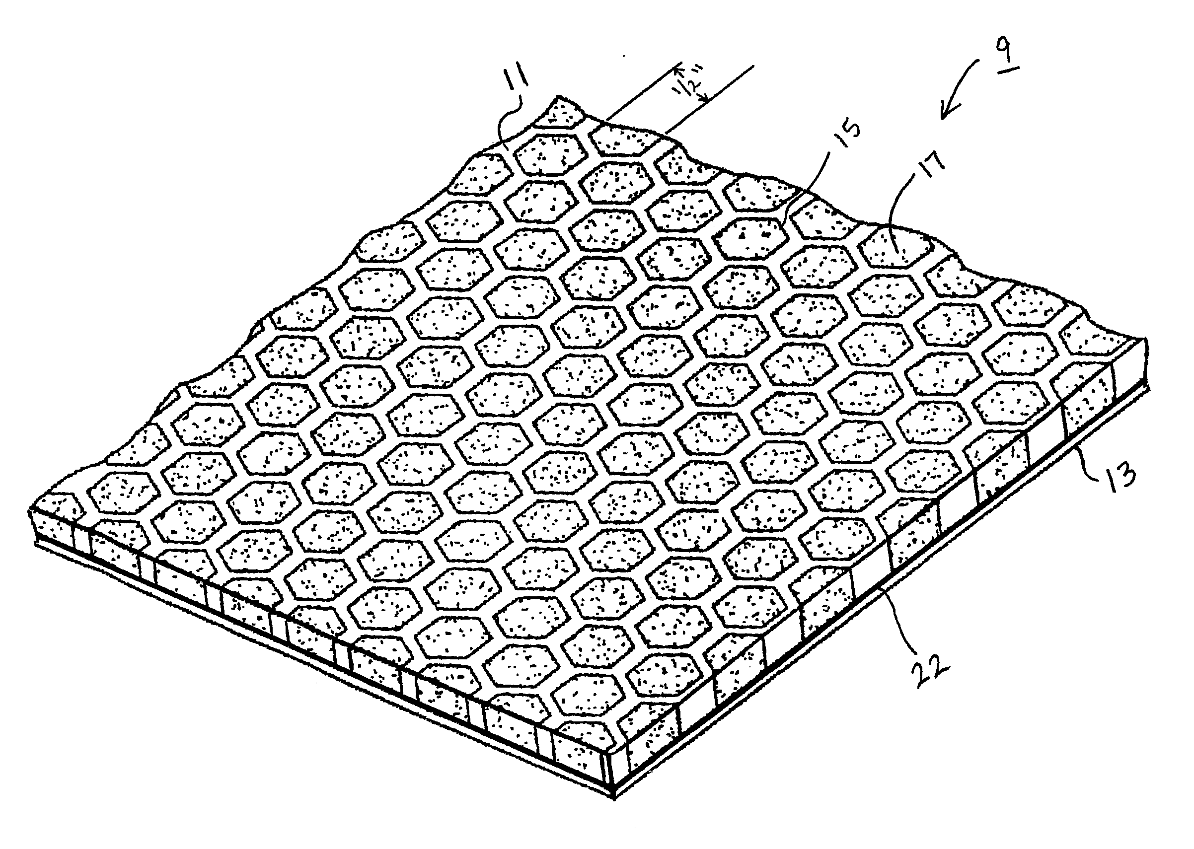
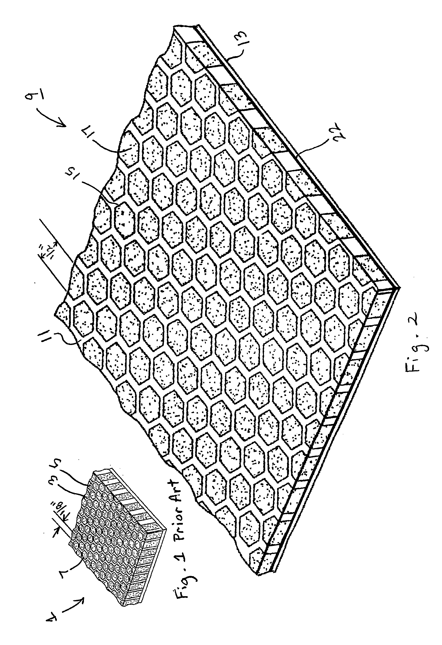
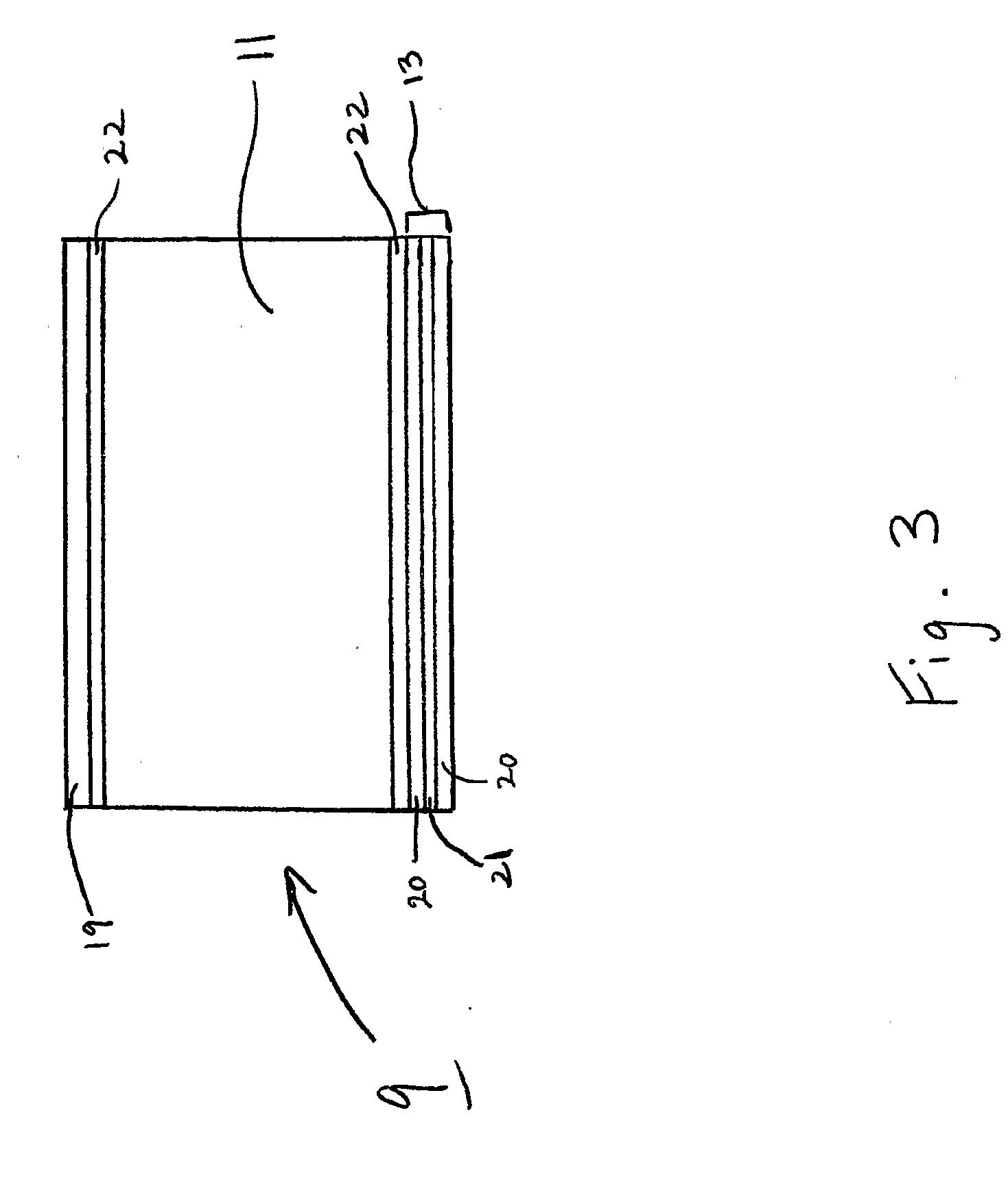
[0021] Referring now to FIGS. 2 and 3 in the drawings, a partial perspective view and a schematic representation of the preferred embodiment of a radar-absorbing panel 9 according to the present invention are illustrated, respectively. As illustrated in FIG. 2, panel 9 comprises a honeycomb core 11 and a lower skin 13 attached to the bottom of core 11. As seen in FIG. 2, core 11 comprises an array of individual cells 15 which are preferably filled with an aerogel 17. Lower skin 13 is typically constructed of a combination of discrete layers of woven fiberglas...


PUM


Abstract

A radar-absorbing panel (9) includes a honeycomb core (11) and a lower skin (13), where the lower skin (13) is attached to the bottom of the honeycomb core (11). The honeycomb core (11) is made up of individual cells (15), which may be filled with aerogel. The individual cells (15) are approximately ½ of an inch in size with polygonal shape.

Description

TECHNICAL FIELD [0001] The present invention relates generally to methods of reducing the infrared and radar signature of a vehicle, specifically to the use of insulative and absorptive materials to reduce the amount of infrared radiation being emitted, and the radar signals being reflected, from certain portions of the vehicle. DESCRIPTION OF THE PRIOR ART [0002] Vehicles involved in military operations have a need to reduce their visibility to opposing forces. This need exists for all methods modem military forces use to detect and target enemies. Examples of such methods include visual detection, audio detection, active and passive radar, and infrared detection. This need to avoid detection is especially critical for aircraft, such as airplanes and helicopters, which have a high likelihood of being targeted by enemy air and ground forces using any and all of the above detection methods. [0003] To the end of reducing the infrared signature of aircraft, a number of methods have bee...

Claims


Application Information

Patent Timeline
22 Nov 2007
Publication
US20070268173A1
IPC
H01Q17/00
CPC
F41H3/00; Y10S428/919; H01Q17/008; H01Q17/00
Inventors
RANDY, WILLIAMS B.