Tag antenna
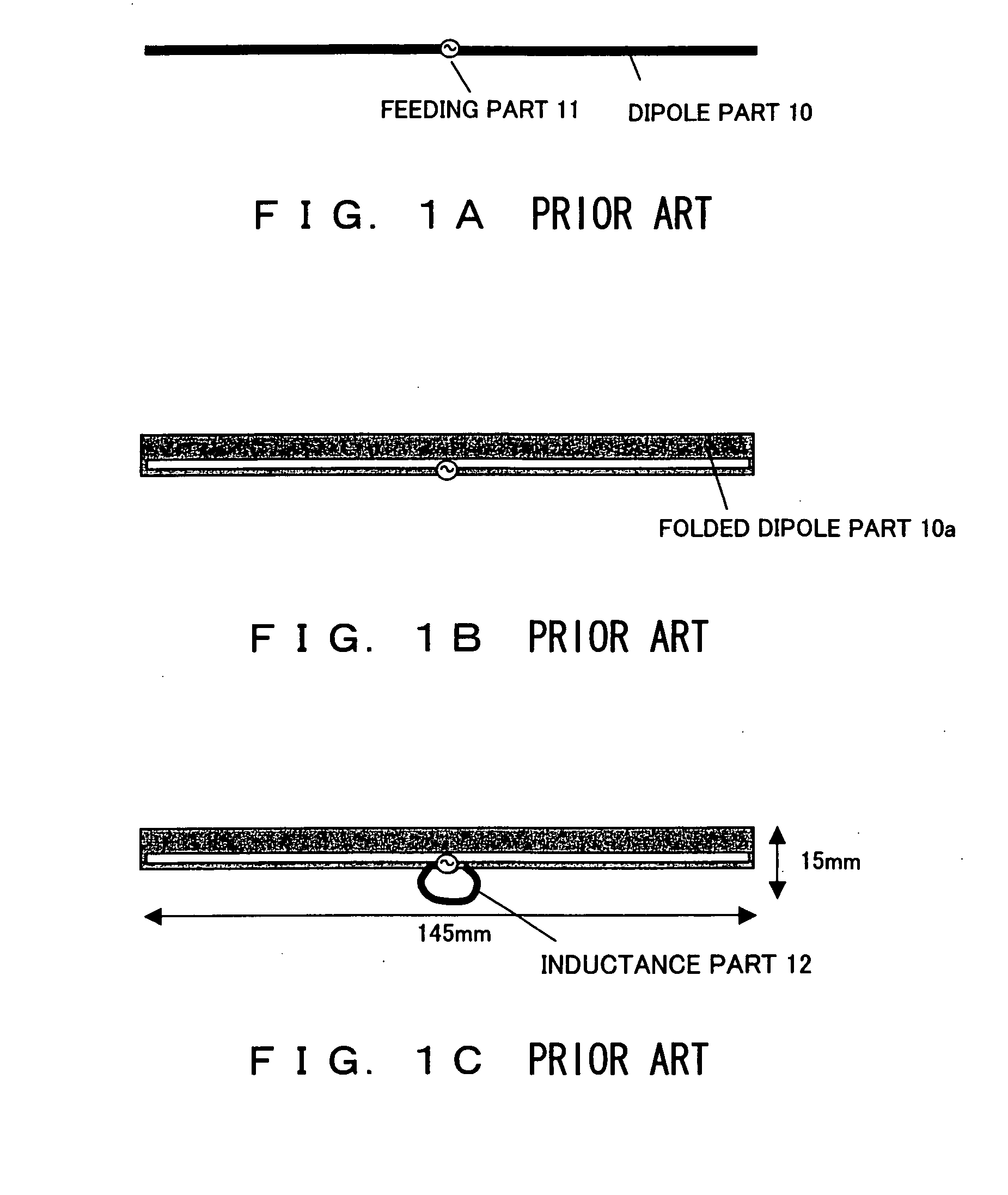
a technology of tag antenna and tag antenna, which is applied in the direction of resonant antenna, record carrier used with machines, instruments, etc., can solve the problems of impracticality, inability to meet the needs of miniaturization, and large height of 15 mm and width of 145 mm, so as to reduce the cost of the antenna
- Summary
- Abstract
- Description
- Claims
- Application Information
AI Technical Summary
Benefits of technology
Problems solved by technology
Method used
Image
Examples
first embodiment
[0039] This is under the assumption that the RFID tag antenna will be used in a UHF band. (The purpose of miniaturization is lost if the operating frequency is 2.45 GHz.) FIG. 4 to FIG. 11 are diagrams explaining the present invention.
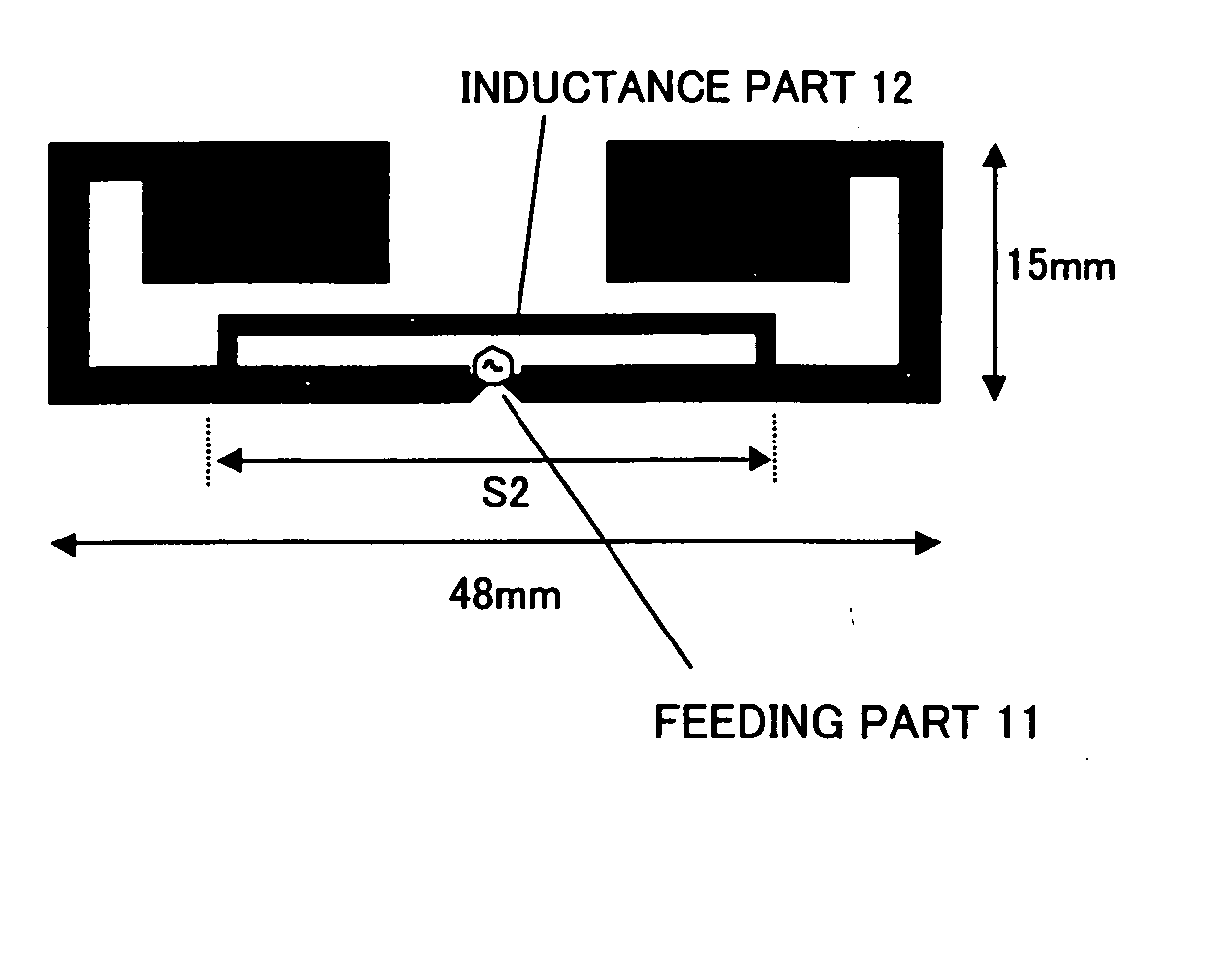
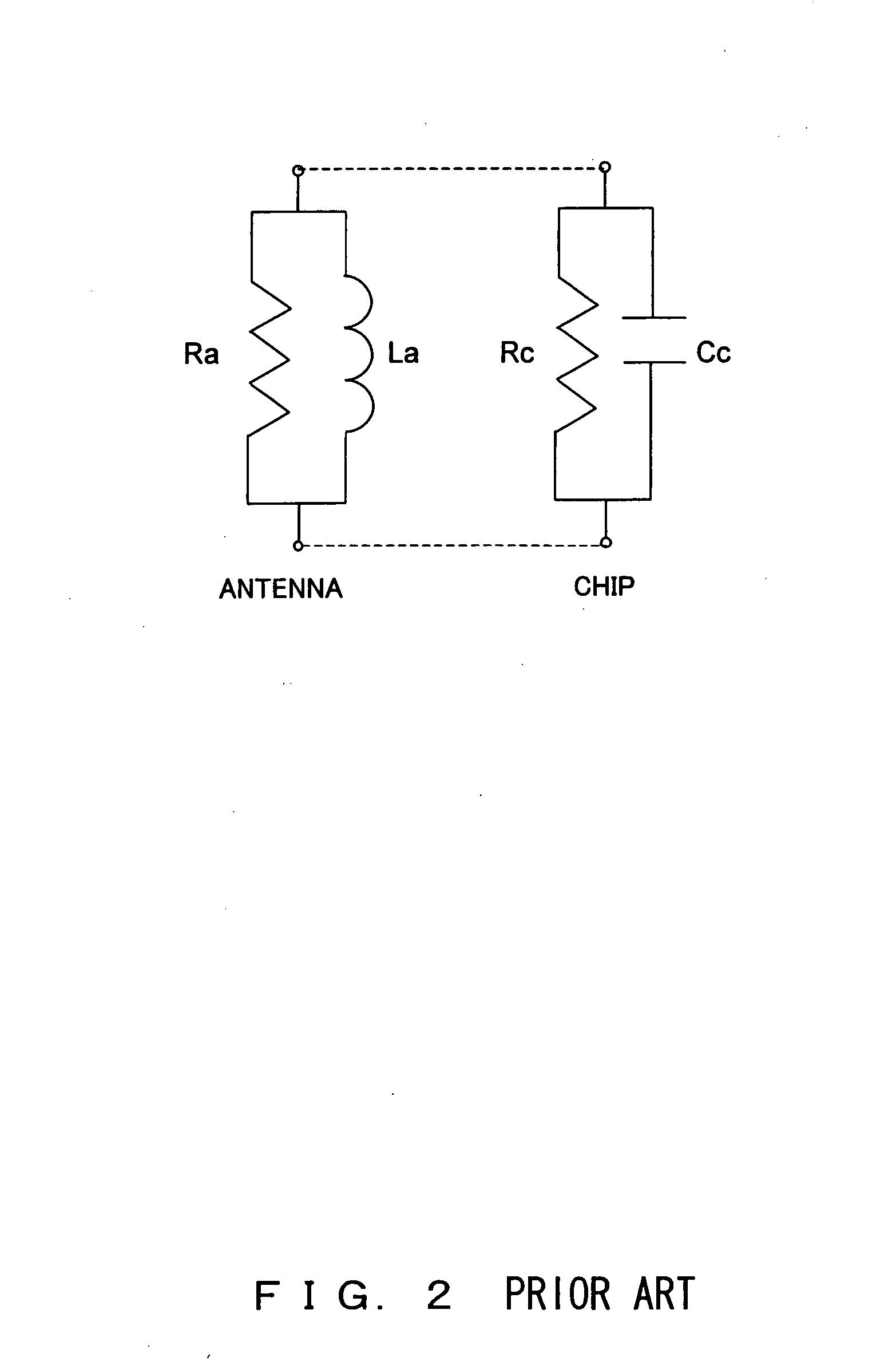
[0040] As shown in FIG. 6, a dipole is formed with a height of 15 mm×width of 48 mm (effective total length, approximately 116 mm=⅜λ), under the constraint of an area smaller than ¼ of a card area. The antenna in FIG. 3 has a rolled dipole part 10. Electromagnetic field simulation is performed for this antenna configuration, and when the calculation results of f=700 MHz to 3000 MHz are plotted on an admittance chart, a trajectory (antenna without L) such as the thin line of FIG. 4 is formed. At the imaginary part=0, f=1340 MHz, which is large, and Ra=16 Ω, because the RFID tag antenna is miniaturized. Generally, if the dipole is bent, the radiation resistance Ra becomes smaller than the Ra=72 Ω of an ordinary straight dipole. In this case, the f=953 MH...
second embodiment
[0046]FIG. 12A to FIG. 14 are diagrams explaining the present invention.
[0047] In RFID, the tag antenna may be implemented adhered to a target object. In this case, the most suitable inductance must be selected very carefully because the resonance wavelengths change due to the specific dielectric constant (εr) of the object to which it is adhered.
[0048] As shown in FIG. 12A, the dipole was formed with a height of 10 mm and a width of 60 mm (effective total length, approximately 75 mm=λ / 4) and designed using electromagnetic simulation and experimental product measurements with the same considerations as the first embodiment. The thickness of the object to which the antenna is adhered is assumed to be t=1 mm and the specific dielectric constant to be εr=1, 3, or 5 (air is εr=1, plastic is εr=3 to 4, and rubber is εr=4 to 5). As a result, the inductance La of the antenna to the inductance length S2 is the value shown in FIG. 13. Because it is known from the first embodiment that the a...
third embodiment
[0053]FIG. 15 to FIG. 21 are diagrams explaining the present invention.
[0054] As shown in FIG. 15, under the assumption that the size is half of a card size, a bow-tie-shaped dipole (Bow Tie part 13) was formed with a height of 37 mm and a width of 48 mm (effective total length, approximately 110 mm=⅜λ) and designed using electromagnetic simulation and experimental product measurements with the same considerations as the first embodiment. As a result, the La value became that shown in FIG. 16 as a function of the inductance length S1. Because it is known from the first embodiment that the actual measurement and the simulation value for inductance almost match, this simulation value is reliable. In addition, from the results of the experimental production of the antenna, the antenna radiation resistance is Ra=1150 Ω regardless of the S1 value. Further, the simulation value of the gain is the value shown in FIG. 14. Because the area of the dipole part is larger than that of the antenn...
PUM
 Abstract
Description
Claims
Application Information
 - R&D
- Intellectual Property
- Life Sciences
- Materials
- Tech Scout
- Unparalleled Data Quality
- Higher Quality Content
- 60% Fewer Hallucinations
Browse by: Latest US Patents, China's latest patents, Technical Efficacy Thesaurus, Application Domain, Technology Topic, Popular Technical Reports.
© 2025 PatSnap. All rights reserved.Legal|Privacy policy|Modern Slavery Act Transparency Statement|Sitemap|About US| Contact US: help@patsnap.com


