
High efficiency radio isotope energy converters using both charge and kinetic energy of emitted particles

a radio isotope and converter technology, applied in the direction of generators/motors, nuclear engineering problems, nuclear engineering, etc., can solve the problems of limiting the extent to which the overall device size can be shrunk, conventional batteries have a relatively short useful life, and the use efficiency of autonomous microsystems is hindered, so as to improve the efficiency of the radioactive powered mechanical reciprocating beam

Inactive Publication Date: 2007-11-29
CORNELL RES FOUNDATION INC
View PDF16 Cites 34 Cited by
  • Summary
  • Abstract
  • Description
  • Claims
  • Application Information

AI Technical Summary

Benefits of technology

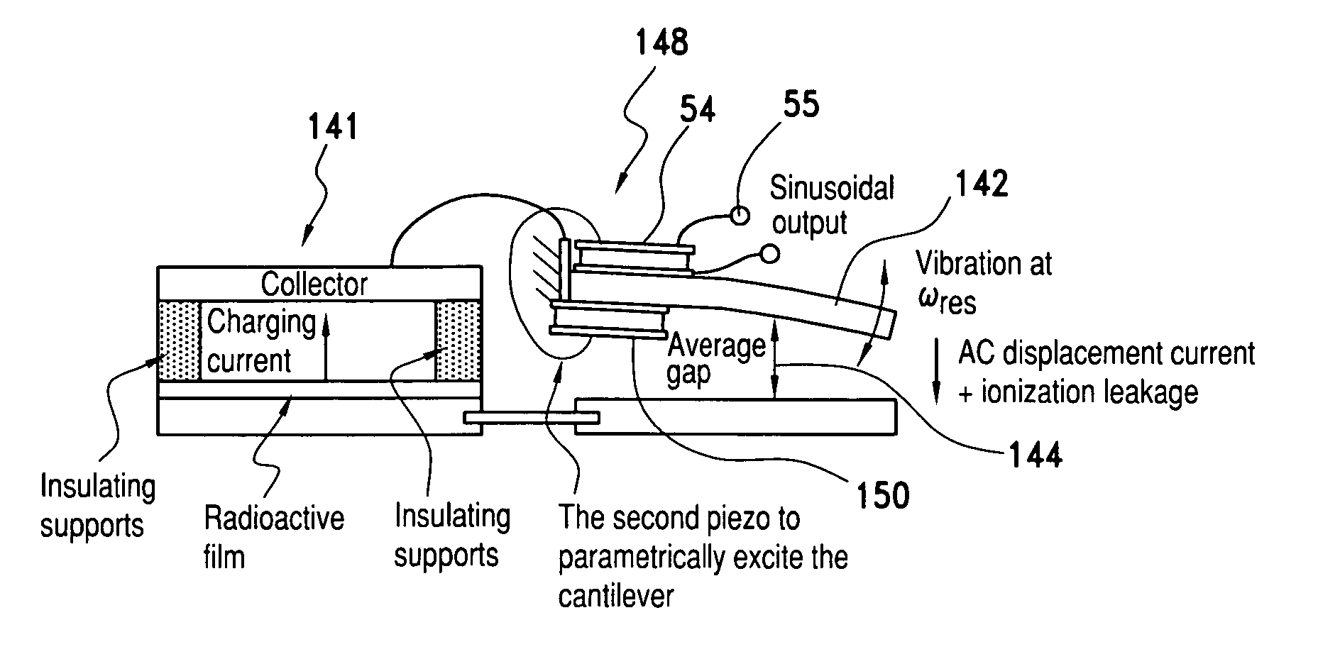
"The invention provides structures and methods to improve the efficiency of a radioactive powered mechanical reciprocating beam. The first embodiment involves carrying a betavoltaic cell on the electron collector cantilever beam to provide a continuous power output that can be added to the piezo-electric circuit's alternating current (AC) power output. The second embodiment involves using a separate capacitor that shares charge with the radioactive thin film and the collector. Additionally, a piezoelectric element is included at the bases of the cantilever arrays to allow for continuous small mechanical reciprocation without full contact across the capacitor. These improvements enhance the efficiency of the power generation process and provide a more reliable and continuous power output for electronic circuits."

Problems solved by technology

However, such systems still require a power source, and the utility of autonomous Microsystems has been hindered by the unavailability of suitable power sources that provide enough power while not greatly increasing the final volume of the system.
Even the smallest conventional batteries may be much larger than the MEMS system being supplied with power, thus limiting the extent to which the size of the overall device can be shrunk.
In addition, conventional batteries have a relatively short useful lifetime, typically on the order of days to weeks or at most months, whereas in some applications it would be desirable to have a power source capable of supplying power to the MEMS device for many months or even years.
Further, as devices shrink in size, the surface to volume ratio increases, with large losses from radiative and convective losses.
Consequently, it is unlikely that traditional thermal conversion will work in microscale devices.
However, a significant disadvantage is that the high energy of the particles damages the crystal lattice, which in turn reduces the effectiveness of the capture of more particles.
Although there are ways to continuously or intermittently thermally anneal the crystal, it is unlikely that such annealing will result in a fully repaired crystal and it is a process that is difficult to utilize in devices that are in place in the field.
Furthermore, because such sources depend on the use of pn-junctions, the operating temperature range of the devices is limited to about −15.degree. C. to 100.degree. C.
However, such an approach requires very high radioactive source levels due to the low efficiency of the incident particle-to-photon production, and the consequent absorption of the photons within the photon generating layer.
Consequently, such an approach would only provide useful output voltages if the load capacitance is of the same order of magnitude as that of the source-collector capacitor.
While the '920 patent demonstrated certain operational principles, the efficiency of the structure is undesirably limited.

Method used


Image

  • High efficiency radio isotope energy converters using both charge and kinetic energy of emitted particles
  • High efficiency radio isotope energy converters using both charge and kinetic energy of emitted particles
  • High efficiency radio isotope energy converters using both charge and kinetic energy of emitted particles

Examples


Embodiment Construction

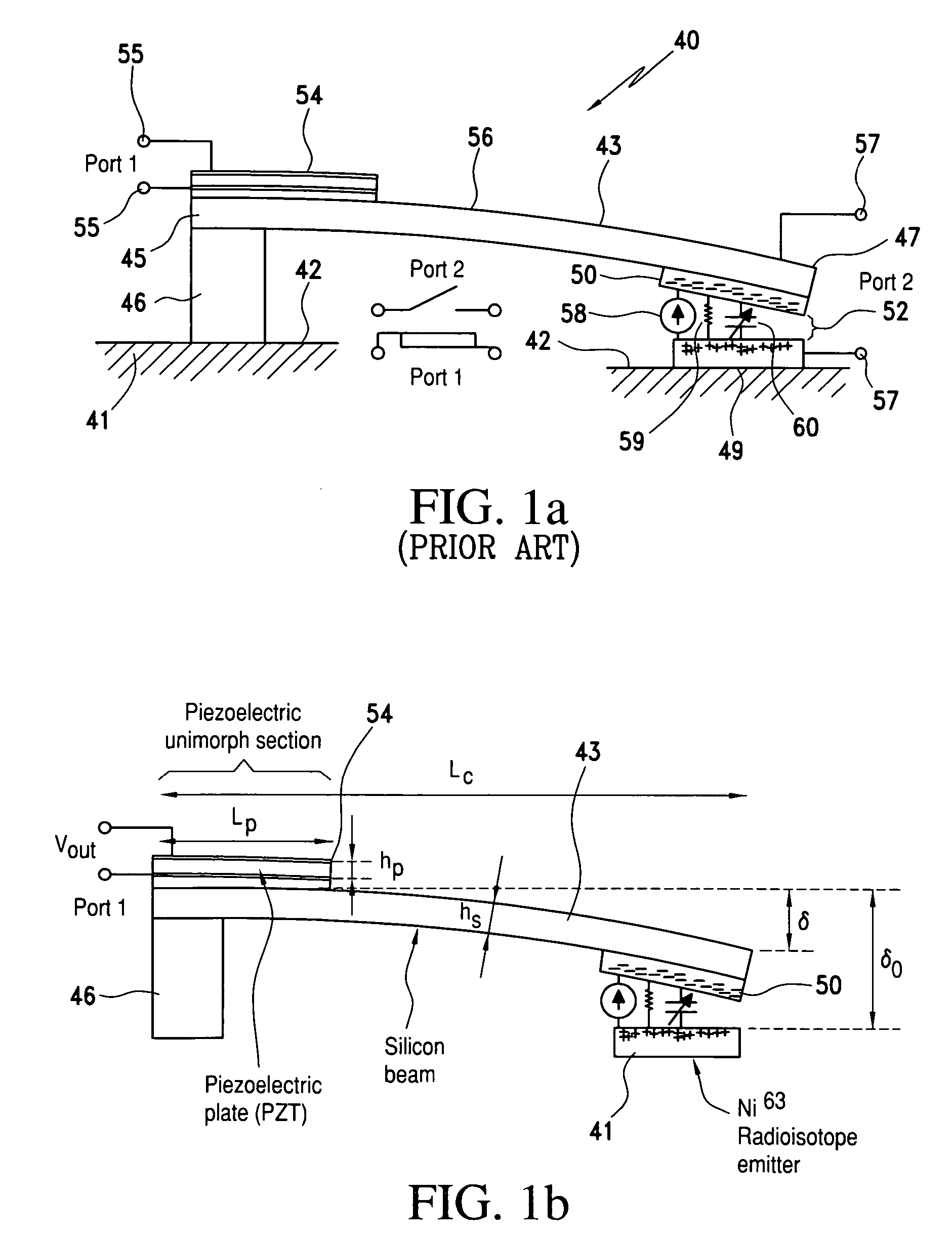
[0037] Referring again to U.S. Pat. No. 6,479,920 FIG. 1a, for nomenclature, a collector 50 collects the electrons emitted by the structure 57 containing the radioactive thin film. As the electrons are emitted, a voltage builds up between collector 50 and 57 which electrostatically deforms the top cantilever. Eventually the plates touch each other and the vibration of the cantilever leads to power generation by the piezoelectric assembly 54-55. The reciprocation time of the cantilever assembly is a function of the charging current, the leakage current, and the mechanical properties such as the spring constant of the composite cantilever and the initial gap. The energy carried by particles emitted by radioactive decay in a radioisotope is captured and converted to mechanical potential energy that is stored in the elastically deformable element or cantilever 43. The release of the energy stored in the deformable element can be utilized to activate other mechanical parts directly or ca...


PUM


Abstract

An electrical energy generator with improved efficiency has a base on which is mounted an elastically deformable micromechanical element that has a section that is free to be displaced toward the base. An absorber of radioactively emitted particles is formed on the base or the displaceable section of the deformable element and a source is formed on the other of the displaceable section or the base facing the absorber across a small gap. The radioactive source emits charged particles such as electrons, resulting in a buildup of charge on the absorber, drawing the absorber and source together and storing mechanical energy as the deformable element is bent. When the force between the absorber and the source is sufficient to bring the absorber into effective electrical contact with the source, discharge of the charge between the source and absorber allows the deformable element to spring back, releasing the mechanical energy stored in the element. An electrical generator of improved efficiency includes a first energy source comprising a piezoelectric transducer secured to the deformable element to convert the released mechanical energy to electrical energy. A second energy source comprises a betavoltaic cell carried on the deformable element or electron collector cantilever beam to provide a direct current (DC) power output that can be added to the piezo-electric circuit's alternating current (AC) power output, such that there is a continuous power output that can be used to provide power to electronic circuits.

Description

[0001] This application is a continuation of and claims priority to the filing date of U.S. provisional application Ser. No. 60 / 701,506 filed Jul. 22, 2005, the entire disclosure of which is incorporated herein by reference. This application is also related to U.S. Pat. No. 6,479,920, to Lal et al, (“the '920 patent”) and for background and enablement purposes, the entire disclosure of the '920 patent is incorporated herein by reference.BACKGROUND OF THE INVENTION [0002] 1. Field of the Invention [0003] The present invention relates to radioactive power sources and micromechanical and microelectromechanical (MEM) devices of improved efficiency. [0004] 2. Discussion of the Prior Art [0005] Microelectromechanical (MEM) devices and microelectromechanical systems (MEMS) are being developed to accomplish a number of previously unattainable goals in systems that are smaller in volume and power consumption than systems contemplated in the prior art. Recently, it has become possible to fabr...

Claims


Application Information

Patent Timeline
Patent Type & Authority Applications(United States)
IPC IPC(8): H01L41/00H10N30/00
CPCG21H1/02G21H1/06H02N2/186G21Y2004/30H02N2/181G21Y2002/201
Inventor LAL, AMITDUGGIRALA, RAJESHLI, HUI
Owner CORNELL RES FOUNDATION INC
Learn More