Arc Quenching Device For A Solar Array

a solar array and quenching device technology, applied in the direction of electric variable regulation, process and machine control, instruments, etc., can solve the problems of permanent power loss of the spacecraft, significant degradation of the performance of the spacecraft, power loss of the full solar array wing, etc., to reduce the risk of significant power loss.

Inactive Publication Date: 2007-11-29
EUROPEAN SPACE AGENCY
View PDF8 Cites 94 Cited by
  • Summary
  • Abstract
  • Description
  • Claims
  • Application Information

AI Technical Summary

Benefits of technology

[0010] An object of the present invention is to minimize the risk of a significant power loss resulting from failure propagation following an uncontrolled arcing event on the solar array or within the solar array drive mechanism. This object is achieved by a device for protecting against arcing events, solar array panels and control equipment supplying a main power bus, said control equipment comprising a regulator for controlling a solar array voltage and including a power dump stage for shunting said solar array voltage as a function of a control signal.
[0014] According to an aspect of the invention, said arc-quenching circuit further comprises means for shaping said output signal so as to provide a short initial delay without any action subsequent to a voltage drop detection provided by said voltage drop detection signal, and after said initial delay an arc-quenching pulse which triggers said power dump stage so as to shunt said solar array voltage.

Problems solved by technology

Over recent years, satellite power bus voltages have increased and several cases of power losses have been observed in satellite on-board electrical systems, resulting in a significant degradation of the spacecraft performances.
These power losses have been attributed to damage caused by sustained voltage arcing occurring either on a solar array panel or even within the solar array drive mechanism causing the power loss of a full solar array wing.
The initiating mechanism of this voltage arcing is usually attributed to some form of contamination.
If the latter situation proves to be the case, the extreme heat generated by the arcing event will rapidly degrade any local insulation barrier and quickly results in a permanent short circuit condition, resulting in a permanent power loss for the spacecraft.

Method used


Image

  • Arc Quenching Device For A Solar Array
  • Arc Quenching Device For A Solar Array
  • Arc Quenching Device For A Solar Array

Examples


Embodiment Construction

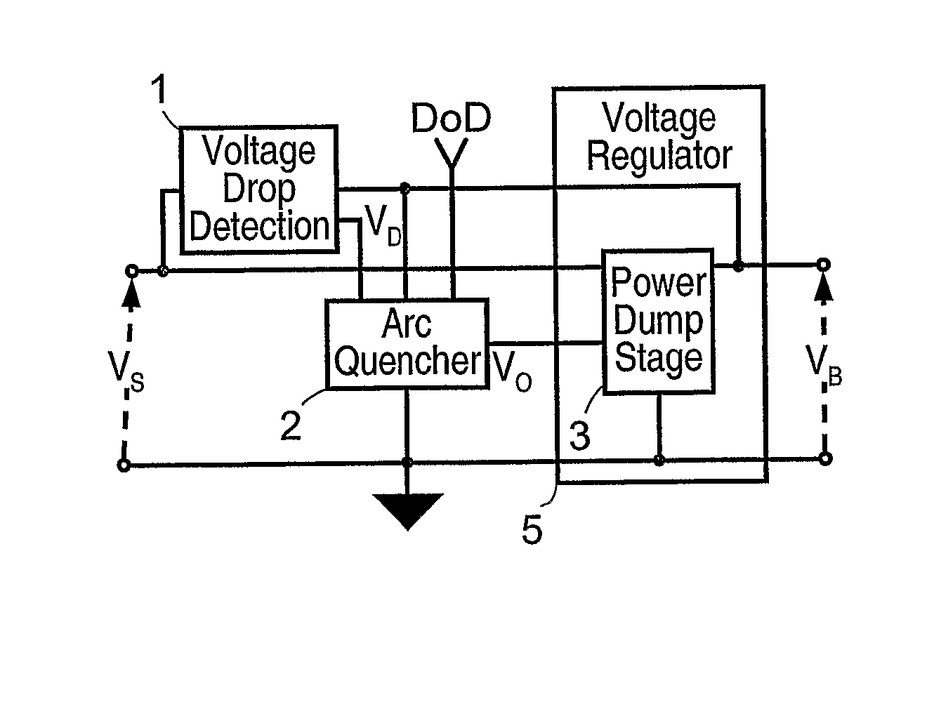
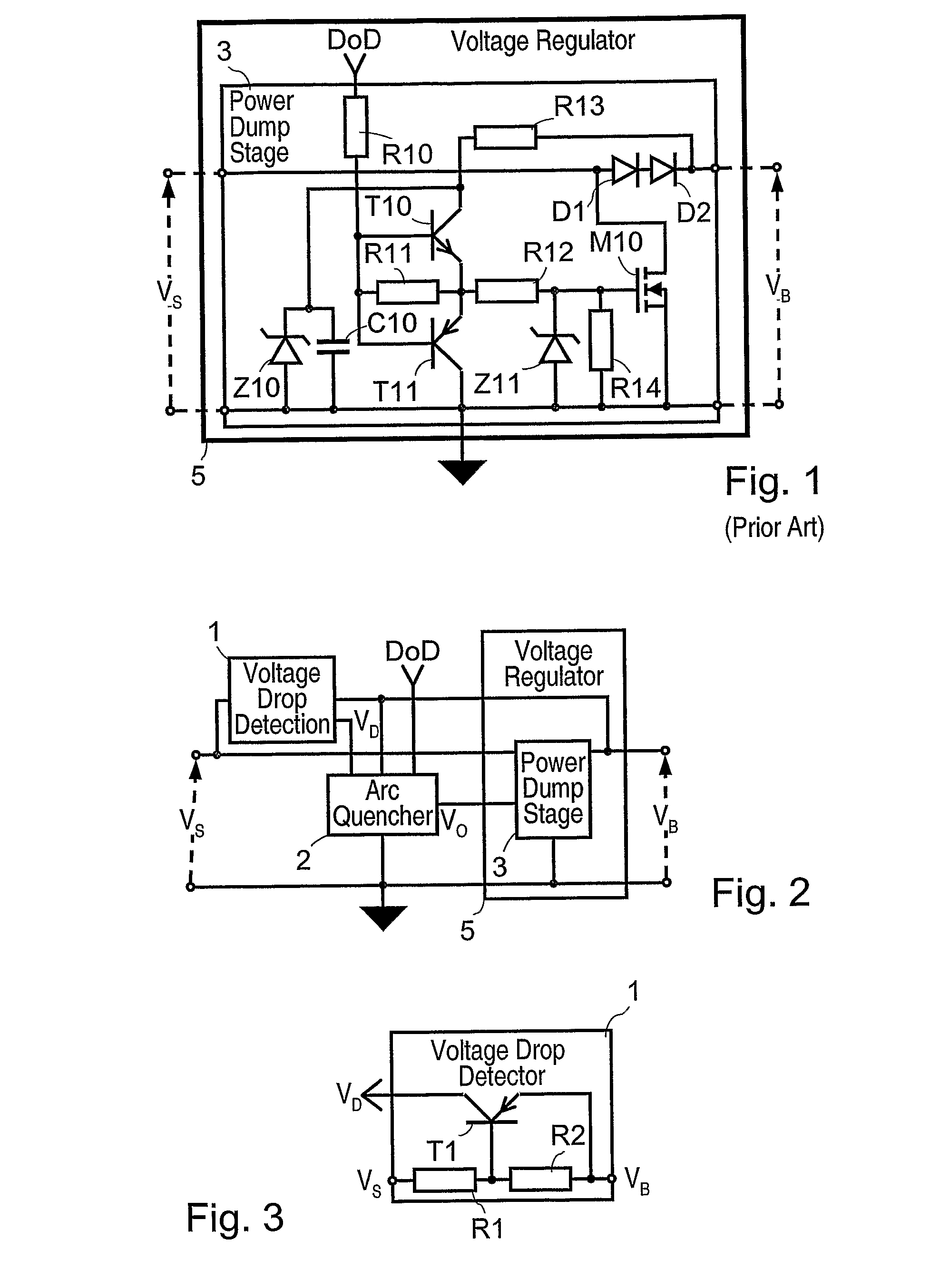
[0026] The major characteristics of the invention will now be detailed. FIG. 2 depicts a protection device associated to a voltage regulator 5 including the power dump stage 3 as the one shown in FIG. 1. According to the present invention the protection device comprises a voltage drop detection circuit 1 for detecting a voltage drop caused by an arcing event occurring in the solar array voltage, and an arc-quenching circuit 2 which uses a detection signal provided by the voltage drop detection circuit to generate a pulse which can activate the power dump circuit 3 into the “ON” state for a certain amount of time.

[0027] The voltage drop detection circuit 1 is shown in detail in FIG. 3. This circuit comprises a transistor T1 of the type pnp having a base terminal connected to the solar array voltage VS through a resistor R1 and to the bus voltage VB through a resistor R2, an emitter terminal connected to the bus voltage and a collector terminal providing a voltage drop detection sign...


PUM


Abstract

A device for protecting against arcing events solar array panels and control equipment supplying a main power bus is provided. The control equipment comprises a regulator for controlling a solar array voltage (VS) and includes a power dump stage for shunting the solar array voltage as a function of a control signal. The device comprises a voltage drop detection circuit for generating a voltage drop detection signal (VD) when a voltage drop is detected in the solar array voltage (VS), and an arc-quenching circuit comprising a system for generating an output signal (VO) which is applied as the control signal to the power dump stage so as to shunt the solar array voltage (VS) when a voltage drop is detected by the voltage drop detection circuit.

Description

BACKGROUND OF THE INVENTION [0001] 1. Field of the Invention [0002] The present invention relates to solar power sources, their regulators and in particular to a circuit to protect against arcing on solar panels or within the solar array drive mechanism (SADM) of a spacecraft. [0003] 2. Description of the Prior Art [0004] Solar array panels of a geostationary telecommunication satellite are maintained in a sunlight configuration by a solar array drive mechanism which rotates the array wings once every 24 hours. In order to transfer the power generated by the solar cells to the satellite on-board electrical system, a slip ring and pick-off brush assembly is incorporated within the solar array drive mechanism. Such a slip ring comprises concentrical conductor rings separated by insulating barriers. [0005] A classical power system of a spacecraft comprises a power regulator for regulating the voltage of the main power bus of the spacecraft. This regulator includes several power dump st...

Claims


Application Information

Patent Timeline
Patent Type & Authority Applications(United States)
IPC IPC(8): G05F1/613B64G1/44B64G1/54H01L31/042
CPCB64G1/443B64G1/546H02S40/34H02H1/0015H01L31/02021Y02E10/50
Inventor HAINES, JAMES EDWARD
Owner EUROPEAN SPACE AGENCY
Why Eureka
Try Eureka