Apparatus and method for packet forwarding in layer 2 network

a packet forwarding and layer 2 technology, applied in the field of packet forwarding apparatus and system forming a layer 2 network, can solve the problems of reducing the efficiency of data transmission across the access network and transit network, and not always being able to provide the communication service desired by users. the effect of the payload length in each frame and improving the efficiency of data transmission across the access network and the transit network

Inactive Publication Date: 2007-11-29
HITACHI LTD
View PDF3 Cites 43 Cited by
  • Summary
  • Abstract
  • Description
  • Claims
  • Application Information

AI Technical Summary

Benefits of technology

[0029] According to the present invention, since a user terminal attempting to access the Internet can first issue a connection request to the packet forwarding apparatus (L2GW) by PPPOE, it is possible to realize a redundant configuration having a plurality of L2GWs within the transit network.

Problems solved by technology

In such high-speed remote access service, however, the transit network imposes restrictions on the layer 3 packet forwarding service and the service provider is not always able to provide a communication service desired by users.
In some situation, a forwarding packet has to be fragmented when the BAS encapsulates the packet with the PPPOE header and this may result in a decrease in data transfer efficiency.
This poses a problem of decreasing the efficiency of data

Method used


Image

  • Apparatus and method for packet forwarding in layer 2 network
  • Apparatus and method for packet forwarding in layer 2 network
  • Apparatus and method for packet forwarding in layer 2 network

Examples


Embodiment Construction

[0051] An embodiment of a packet forwarding system of the present invention will now be described in detail with reference to the drawings.

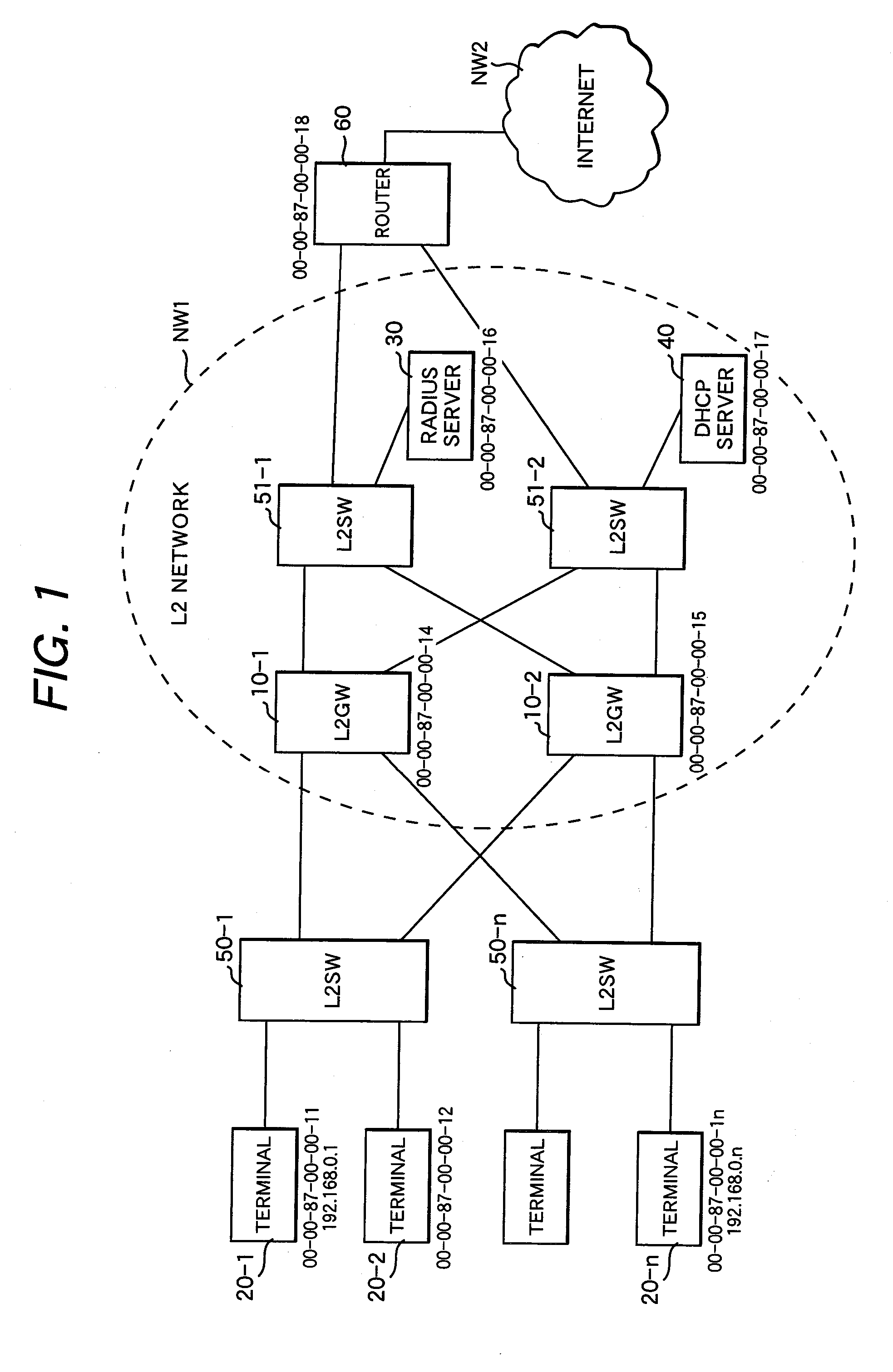
[0052]FIG. 1 shows an example of a configuration of a communication network to which the present invention is applied. The communication network shown here comprises a plurality of L2SWs 50 (50-1, 50-n) forming an access network and a transit network (ISP network) NW1 to which these L2SWs 50 are connected. Each L2SW accommodates at least one user terminal 20 (20-1 to 20-n).

[0053] The transit network (ISP network) NW1 is connected to the Internet NW2 via a router 60. Here, the transit network NW1 is an L2 network for forwarding packets according to a layer 2 header. The transit network NW1 includes an L2SW 51-1 connected to a RADIUS server 30, an L2SW 51-2 connected to a DHCP server 40, and a plurality of packet forwarding apparatus (nodes) L2GWs 10 (10-1, 10-2).

[0054] Each L2SW 50 forming the access network is connected to the multiple L2GWs 1...


PUM


Abstract

A packet forwarding apparatus with a function of registering packet forwarding control information for each user terminal into a user management table during PPPoE connection and authentication phases in which the apparatus carries out predetermined communication procedures with each user terminal. During DHCP and IP forwarding phases following the authentication phase, the packet forwarding apparatus controls packet forwarding based on the user management table. Packets are forwarded in the form of PPPoE frame until the authentication phase is completed and packets are forwarded in the form of Ethernet frame in the DHCP and IP forwarding phases.

Description

CLAIM OF PRIORITY [0001] The present application claims priority from Japanese application serial No. 2006-141455, filed on May 22, 2006, the content of which is hereby incorporated by reference into this application. BACKGROUND OF THE INVENTION [0002] (1) Field of the Invention [0003] The present invention relates to a packet forwarding system and, more particularly, to a packet forwarding apparatus and system forming a layer 2 network and to a packet forwarding method. [0004] (2) Description of Related Art [0005] Nowadays, an authentication-based Internet connection service using high-speed access lines, such as Asymmetric Digital Subscriber Line (ADSL), Fiber to The Home (FTTH), and wireless Local Area Network (LAN) has come into popular use and a communication environment enabling efficient transfer of a large volume of content data to user terminals is being developed. Each user terminal is connected via a high-speed access line to a Broadband Access Server (BAS) located as a h...

Claims


Application Information

Patent Timeline
IPC IPC(8): H04L12/28H04L12/46H04L45/586
CPCH04L12/4625H04L49/35H04L63/0236
Inventor TAKAHASHI, TADASHIMIYATA, HIROAKIYOKOYAMA, TAKASHIKAMATA, MASANORI
Owner HITACHI LTD
Why Eureka
Try Eureka