

Large area patterning using interferometric lithography
a technology of interferometry and lithography, applied in the direction of instruments, photomechanical devices, optical elements, etc., can solve the problems of multiple reflection and diffraction between, high contrast interference patterns,
- Summary
- Abstract
- Description
- Claims
- Application Information
AI Technical Summary
Benefits of technology
Problems solved by technology
Method used
Image

Examples
Embodiment Construction
[0002]1. Field of the Invention
[0003]This invention relates generally to lithography and, more particularly, to methods for patterning large areas using immersion lithography.
[0004]2. Background of the Invention
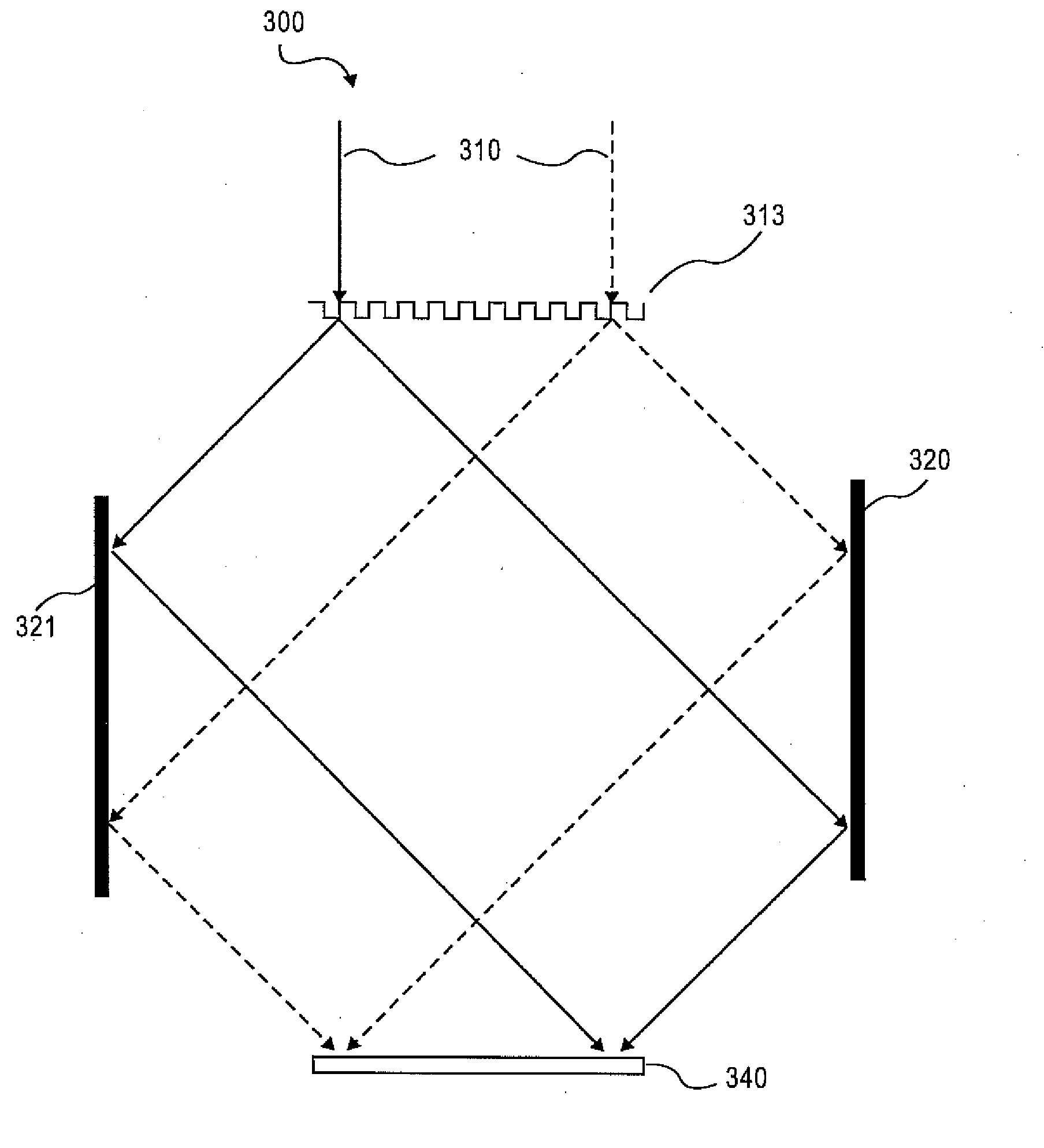
[0005]Interferometric lithography, the use of an interference pattern between two or more coherent laser beams to expose a photosensitive material, is a well-established technique for the production of small features at the linear-system frequency-space limits of optics. See S. R. J. Brueck, Optical and Interferometric Lithography—Nanotechnology Enablers, Proc. IEEE 93, 1704 (2005), which is herein incorporated by reference in its entirety. These extend to a half-pitch of λ(4nlow) where λ is the optical vacuum wavelength and nlow is the lower of the refractive index of the photosensitive material or of any planar material above and in contact with the photosensitive material (thin film or bulk dielectric or fluid with surfaces parallel to the photoresist). In the most familia...
PUM
 Abstract
Description
Claims
Application Information