Continuous Slurry Polymerization Process and Apparatus

a polymerization process and polymerization technology, applied in the direction of chemistry apparatus and processes, chemical/physical/physical-chemical stationary reactors, chemical/physical/physical-chemical processes, etc., can solve the problems of equipment and utilities that are required for their operation and often amount to and can be a significant portion of the cost of producing polymer. , to achieve the effect of eliminating the possibility of downstream equipment plugging, improving safety, and eliminating the plug

Inactive Publication Date: 2007-11-29
EXXONMOBIL CHEM PAT INC
View PDF75 Cites 16 Cited by
  • Summary
  • Abstract
  • Description
  • Claims
  • Application Information

AI Technical Summary

Benefits of technology

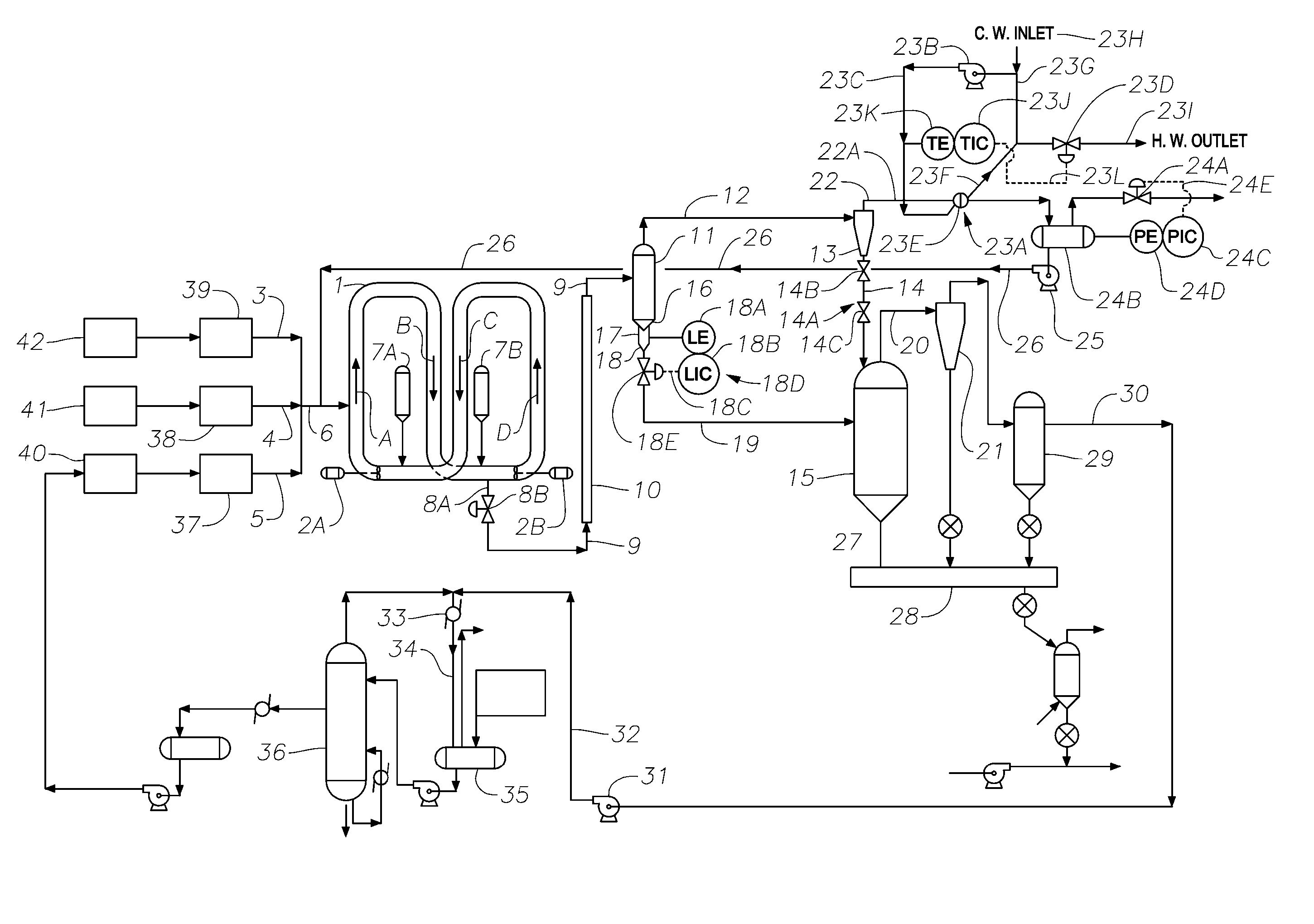
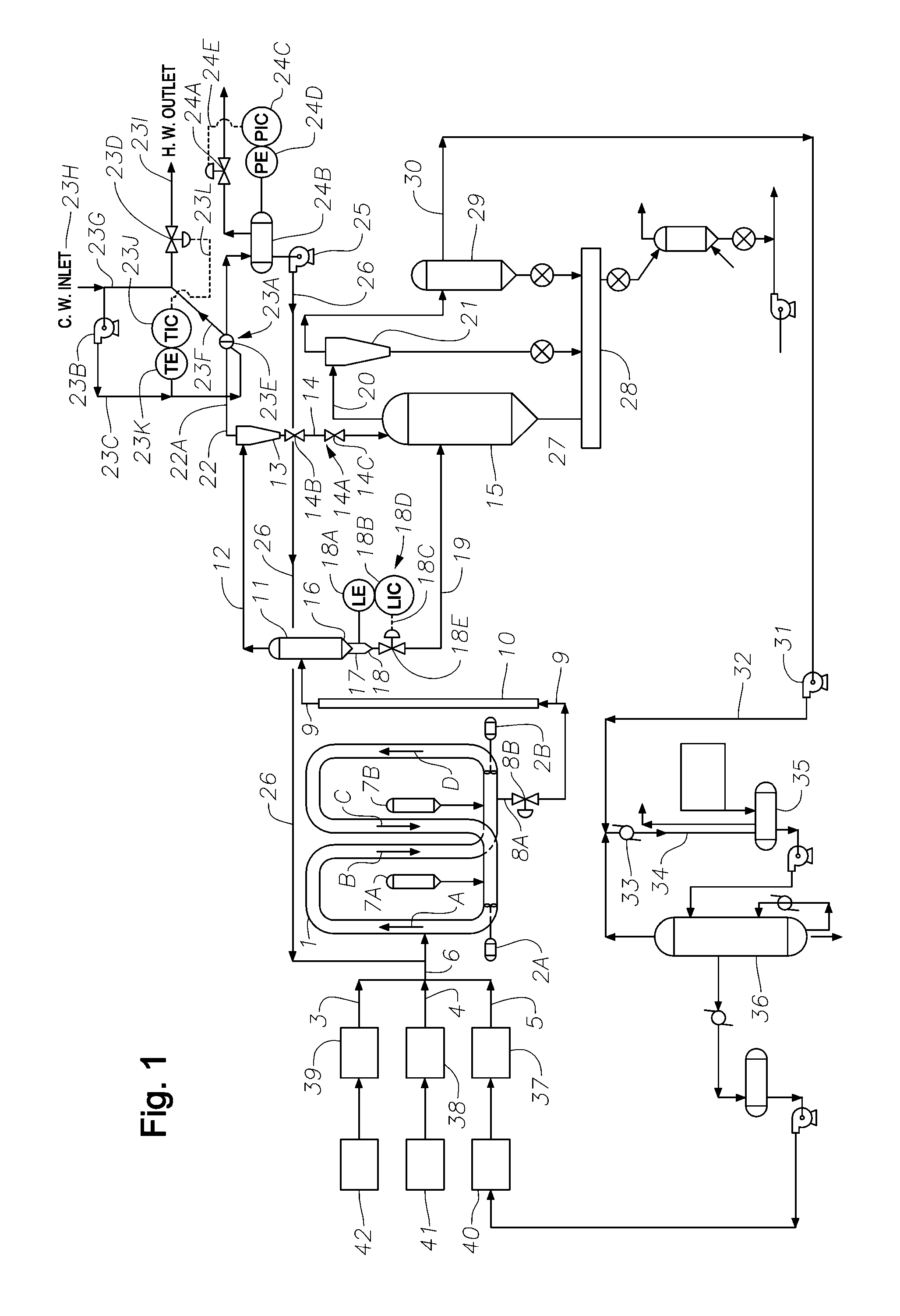
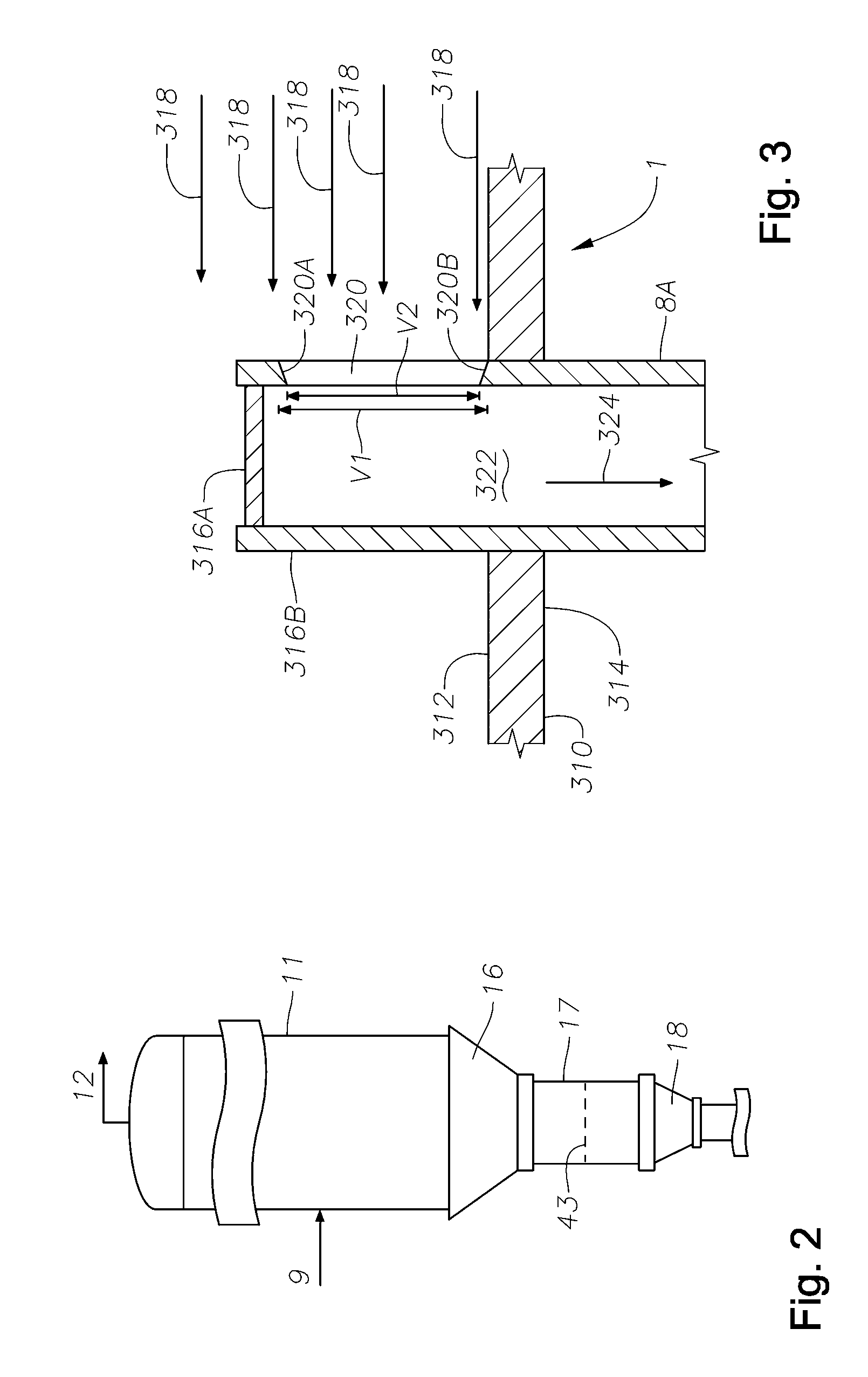
[0027] The invention provides also a method for the continuous removal of a stream of polymerization effluent from a slurry reactor through a discharge valve; increasing the heat content of the polymerization effluent during its transit through the first transfer conduit to a temperature below the fusion point of the polymer while continuously communicating the polymerization effluent to a first flash tank having a bottom defined by substantially straight sides inclined at an angle to the horizontal equal to or greater than the angle of slide of the concentrated polymer solids / slurry; continuously vaporizing from about 50% to about 100% of the liquid medium in the first heated flash tank to yield a concentrated polymer solids / slurry and a vapor stream at such a temperature and pressure that the inert diluent content of the vapor is condensable, without compression, by heat exchange with a fluid having a temperature in the range from about 65° F. to about 135° F.; continuously discharging the concentrated polymer solids / slurry from the first flash tank to a first flash tank exit seal chamber of such a length (l) and diameter (d) that a volume of concentrated polymer solids / slurry is continuously maintained so as to form a pressure seal in the first flash tank exit seal chamber; continuously discharging the concentrated polymer solids / slurry from the first flash tank seal chamber through a seal chamber exit reducer defined by substantially straight sides inclined at an angle to that of horizontal equal to or greater than the angle of slide of the polymer solids which remain after removal of about 50 to 100% of the inert diluent therefrom; communicating a continuous plug flow of concentrated polymer solids / slurry from the first flash tank exit seal chamber through the seal chamber exit reducer to a second transfer conduit which communicates the continuous plug flow of concentrated polymer solids / slurry to a second flash tank; and continuously vaporizing essentially all of any remaining inert diluent and / or unreacted monomer in a second flash tank operated at a lower pressure than the first flash tank; condensing the vaporized inert diluent and / or unreacted monomer from the second flash tank by compression and heat exchange; and continuously discharging the essentially dried polymer slurry from the second flash tank for further processing or storage.
[0043] The claimed apparatus and process provide several advantages over the prior art including: (1) allowing for a continuous processing of the contents of a slurry reactor from the point of discharge of the polymerization slurry effluent through a discharge valve; a first flash tank; a seal chamber; a seal chamber exit reducer; and therefrom to a second flash tank, (2) significantly increasing ethylene concentration in the loop reactor liquid medium thereby increasing reactor through-put, (3) significantly increasing the wt % of polymer solids in the polymerization slurry, (4) significantly increasing reactor space time yield and (5) energy consumption is reduced by reducing the need to compress and / or distill the reactor vapor-liquid effluent. Recycling compressors and other downstream equipment can be reduced in size or eliminated.

Problems solved by technology

The cost of compression equipment and the utilities required for its operation often amounts to a significant portion of the expense involved in producing polymer.
The equipment and utilities costs for distillation and treatment can be a significant portion of the cost of producing the polymer.

Method used


Image

  • Continuous Slurry Polymerization Process and Apparatus
  • Continuous Slurry Polymerization Process and Apparatus
  • Continuous Slurry Polymerization Process and Apparatus

Examples


example 1

[0123] A typical ethylene polymerization process can be conducted at a temperature of about 215° F. and a pressure of 565 psia. An example of such a process would result in a polymerization effluent of about 83,000 pounds per hour comprising about 45,000 pounds per hour of polyethylene polymer solids and about 38,000 pounds per hour of isobutane and unreacted monomers. The continuously discharged polymerization effluent is flashed in the first flash tank at a pressure of about 240 psia and a temperature of about 180° F. to remove overhead about 35,000 pounds per hour of diluent and unreacted monomer vapors and entrained particulates. Auxiliary heat to impart an additional quantity of heat to the polymerization effluent is supplied by appropriate heating means during the transit between the discharge valve and the first flash tank. After removal of the fines, the isobutane vapor is condensed, without compression, by heat exchange at a pressure of about 240 psia and a temperature of a...

example 2

[0124] A typical ethylene polymerization process can additionally be conducted at a temperature of about 215° F. and a pressure of 565 psia. An example of such a process would result in a polymerization effluent of about 83,000 pounds per hour comprising about 45,000 pounds per hour of polyethylene polymer solids and about 38,000 pounds per hour of isobutane and unreacted monomers. The continuously discharged polymerization effluent is flashed in the first flash tank at a pressure of about 240 psia and a temperature of about 175° F. to remove overhead about 23,000 pounds per hour of diluent and unreacted monomer vapors and entrained particulates. After removal of the fines, the isobutane vapor is condensed, without compression, by heat exchange at a pressure of about 240 psia and a temperature of about 112° F. The polymer slurry / solids discharging from the bottom of the first flash tank into the seal chamber form a continuous plug flow of concentrated polymer slurry / solids, which pr...

example 3

[0125] An example of a typical ethylene polymerization process was carried out in an eight leg, 20 inch reactor with settling legs having an overall length of 833 ft and a volume of 11,500 gallons. The reactor was equipped with a single flash tank (requiring 100% compression of all diluent discharged from the reactor), a single 460-480 kilowatt circulating pump having a pump head in the range from 85 ft to 110 ft, producing a circulation rate in the range from 21,000 to 28,000 gallons per minute (gpm) and operated in a discontinuous discharge mode. The polymerization temperature and pressure in the reactor would be between about 215° F. to 218° F. and a pressure of 565 psia.

[0126] In the process of example 3, the reactor slurry density is in the range from 0.555 gm / cc to 0.565 gm / cc, a polymer production rate range from 28,000 pounds to 31,000 pounds per hour while maintaining a reactor solids concentration weight percentage in the range from 46 to 48 with a polymer residence time ...


PUM

PropertyMeasurementUnit
lengthaaaaaaaaaa
lengthaaaaaaaaaa
lengthaaaaaaaaaa

Abstract

A process / apparatus is disclosed for continuously separating a liquid medium comprising diluent and unreacted monomers from a polymerization effluent comprising diluent, unreacted monomers and polymer solids, comprising a continuous discharge of the polymerization effluent from a slurry reactor through a discharge valve and transfer conduit into a first intermediate pressure flash tank with a conical bottom defined by substantially straight sides inclined at an angle to that of horizontal equal to or greater than the angle of slide of the slurry / polymer solids and an exit seal chamber of such diameter (d) and length (l) as to maintain a desired volume of concentrated polymer solids / slurry in the exit seal chamber such as to form a pressure seal while continuously discharging a plug flow of concentrated polymer solids / slurry bottom product of the first flash tank from the exit seal chamber through a seal chamber exit reducer with inclined sides defined by substantially straight sides inclined at an angle to that of horizontal equal to or greater than the angle of slide of the polymer solids which remain after removal of about 50 to 100% of the inert diluent therefrom to a second flash tank at a lower pressure.

Description

CROSS REFERENCE TO RELATED APPLICATIONS [0001] This application is a divisional application of U.S. application Ser. No. 10 / 085,809, filed Feb. 28, 2002, which is a continuation-in-part of U.S. application Ser. No. 10 / 079,226, filed Feb. 19, 2002, now U.S. Pat. No. 6,833,415, which is a continuation-in-part of U.S. application Ser. No. 09 / 955,729, filed Sep. 19, 2001, which is a divisional application of U.S. application Ser. No. 09 / 679,959, now U.S. Pat. No. 6,319,997 filed Oct. 5, 2000, which is a divisional application of U.S. application Ser. No. 09 / 313,818, now U.S. Pat. No. 6,204,344, filed May 18, 1999, which is a continuation-in-part of U.S. application Ser. Nos. 09 / 080,412 and 09 / 081,392, now U.S. Pat. No. 6,281,300, both filed May 18, 1998, which both claim the benefit of U.S. Provisional Application No. 60 / 078,859, filed Mar. 20, 1998. Each application in this chain of priority is incorporated by reference herein in its entirety.FIELD OF INVENTION [0002] The present inven...

Claims


Application Information

Patent Timeline
Patent Type & Authority Applications(United States)
IPC IPC(8): C08F2/00B01J8/00B01J8/20B01J19/18C08F210/16
CPCB01D3/06Y10T29/49826B01J8/005B01J8/0055B01J8/007B01J8/382B01J19/0053B01J19/1837B01J2208/0007B01J2208/00539B01J2208/00548B01J2208/00761B01J2208/00769B01J2208/00867B01J2219/00006B01J2219/00033B01J2219/00103B01J2219/00114B01J2219/00162B01J2219/00164B01J2219/00191B01J2219/002B01J2219/00213B01J2219/00231B01J2219/00236B01J2219/0024C08F2/00C08F6/003C08F10/00C08F210/16B01J8/003Y10T29/53Y10T29/49345Y10S526/943C08F2/01C08F2/14C08F210/14
Inventor KENDRICK, JAMES AUSTINTOWLES, THOMAS W.ROGER, SCOTT THOMAS
Owner EXXONMOBIL CHEM PAT INC
Why Eureka
Try Eureka