Systems and methods for wound area management

a wound and system technology, applied in the field of wound area management, can solve the problems of inability to provide the necessary information to health care providers, inability to accurately measure and track the size of wounds, and high complexity of systems, so as to achieve non-invasiveness, cost effectiveness, and repeatability.

Inactive Publication Date: 2007-11-29
KCI LICENSING INC
View PDF32 Cites 78 Cited by
  • Summary
  • Abstract
  • Description
  • Claims
  • Application Information

AI Technical Summary

Benefits of technology

[0018] It would therefore be desirable to have a wound measurement system that achieved all of the goals mentioned above, namely; accuracy, discrimination (the ability to distinguish the wound area from the periwound area), repeatability, non-invasiveness, simplicity, and cost effectiveness. Those parts of the system that might come in direct contact with the patient should be aseptic and disposable. The processing components of the system should be straightforward and intuitive to use by modestly skilled clinicians. The processing components should likewise be capable of providing historical data to allow the user to track changes over time.
[0020] The method associated with the system described includes initially tracing the perimeter of the wound on a transparent or translucent film in a manner already known to most clinicians in the field. Rather than re-tracing the outline a second time however, the transparency is positioned on a simple template that allows both scaling and off angle positioning in the imaging process. The digital imaging device of the system of the first preferred embodiment described above, captures the entire template with the wound trace contour inside. The digitized image is then processed by software within the unit to automatically find the template reference features and the trace and displays certain results on a display screen. The processing system of the present invention may also include the steps of image data thresholding, contour finding, square finding (used to identify the template), setting the region of interest (associated with the reference features on the template), wound trace finding, calculating the areas, eliminating distortion, and displaying the result with certain types of data filtering.
[0021] By using a digital camera or other imaging device it is possible to simplify the data input process and also to avoid errors caused by the manual second tracings associated with previous systems. The imagining method is also much more flexible than using a fixed-size touch sensitive pad. Positioning the wound trace in association with the template also makes the image processing much more reliable and accurate. The method of the present invention can further be used to measure multiple areas of a wound in a given region of tissue. The digital imaging device quality and processing power requirement of the system of the present invention are relatively low so the methodology can be embedded into a single simple microprocessor system. In contrast to the prior art, the present method uses a digital camera to capture the traced wound contour and then calculates the area by comparing it with the known size reference template features. There is no second tracing, and the wound size is only limited to the size of the template used. By changing the low cost template, the method can be used for any wound. The use of the template with reference features of known dimensions allows the imaging process to both scale the image and account for other than normal to the surface viewing angles.
[0023] The method associated with the second preferred embodiment described above includes placing a small reference tag on the patient adjacent (but preferably outside) the wound and capturing a digital image of the wound site from a position generally normal to the plane of the wound area. The digital image is then transferred to a tablet PC or other computer having a display screen and a graphical data input device associated with the display screen (such as a touch sensitive panel). Preferably the display can be positioned for both viewing and for graphical data input. If the display is associated with a tablet PC, for example, it may be positioned to lay flat on a writing surface such as a desk. The image is then displayed on the screen of the PC and scaled (enlarged or reduced) to provide the clinician with an accurate view of the wound. The clinician then traces the wound perimeter with a stylus on the screen (or other type of graphical data input device) to define the extent of the wound. Software within the system then calculates the area of the wound based on the traced outline and the scale of the image (as referenced to the tag that is included in the field of view). Since the reference tag is designed to be easily recognizable to the computer the scaling can be very accurate. Defining the perimeter of the wound, on the other hand, is not so easy for the computer so this step in the process is left in the hands of the clinician.
[0024] In contrast to the prior art, this second embodiment, like the first, utilizes only a single tracing step and therefore greatly reduces the chance of introducing errors into the process. Unlike prior art methods that utilize touch pad technologies, the embodiment of the present invention described herein is able to beneficially scale the image of the wound before a trace is made by the clinician.

Problems solved by technology

Previous efforts to measure and track changes in the size of a wound have failed in many respects to provide the necessary information to health care providers to allow an assessment of the efficacy of a therapy.
In addition, such systems involve two tracings, one on the patient and then a second on the touch pad, a process that is susceptible to progressive errors and inaccuracies.
These systems tend to be highly complex and to require significantly greater processing capabilities to take into account variations in the angles and distances associated with the imaging view.
In the end, even these complex systems fail because image recognition processes are often unable to accurately and consistently define a wound perimeter.
Such an injury, however, may be much deeper, including the dermis, subcutaneous fat, fascia, muscle, and even bone.
Current problems in the prior art include imperfect methods for actually measuring (directly or indirectly) the size of the wound.
For chronic wounds, this may not occur due to complex and non-uniform healing processes.
Complete wound closure may not be achieved nor be a realistic objective endpoint for judging the outcome for certain chronic wounds.
These techniques all, however, suffer from various problems with accuracy, repeatability, or complexity.
A wound mold, for example, although it provides a highly reliable measurement, is messy and time consuming, uncomfortable, and risks contaminating the wound.
However, this fluid technique is imprecise, can be messy, and is often difficult to carry out.
The wound can also be contaminated with such approaches.
This approach uses a mathematical formula to calculate the volume but suffers frequently from technique variations in the acquisition of the data.
Stereophotogrammetric systems often provide accurate and reproducible measurements of wound size and volume but do so at great expense and complexity.
Such systems were typically limited in size by the template used or by the touch sensitive surface utilized with the instrumentation.
In addition, many of the imaging methods previously used do not work well on a wound that wraps around a limb or is otherwise not in a plane parallel to the CCD array plane of the imaging device.

Method used


Image

  • Systems and methods for wound area management
  • Systems and methods for wound area management
  • Systems and methods for wound area management

Examples


Embodiment Construction

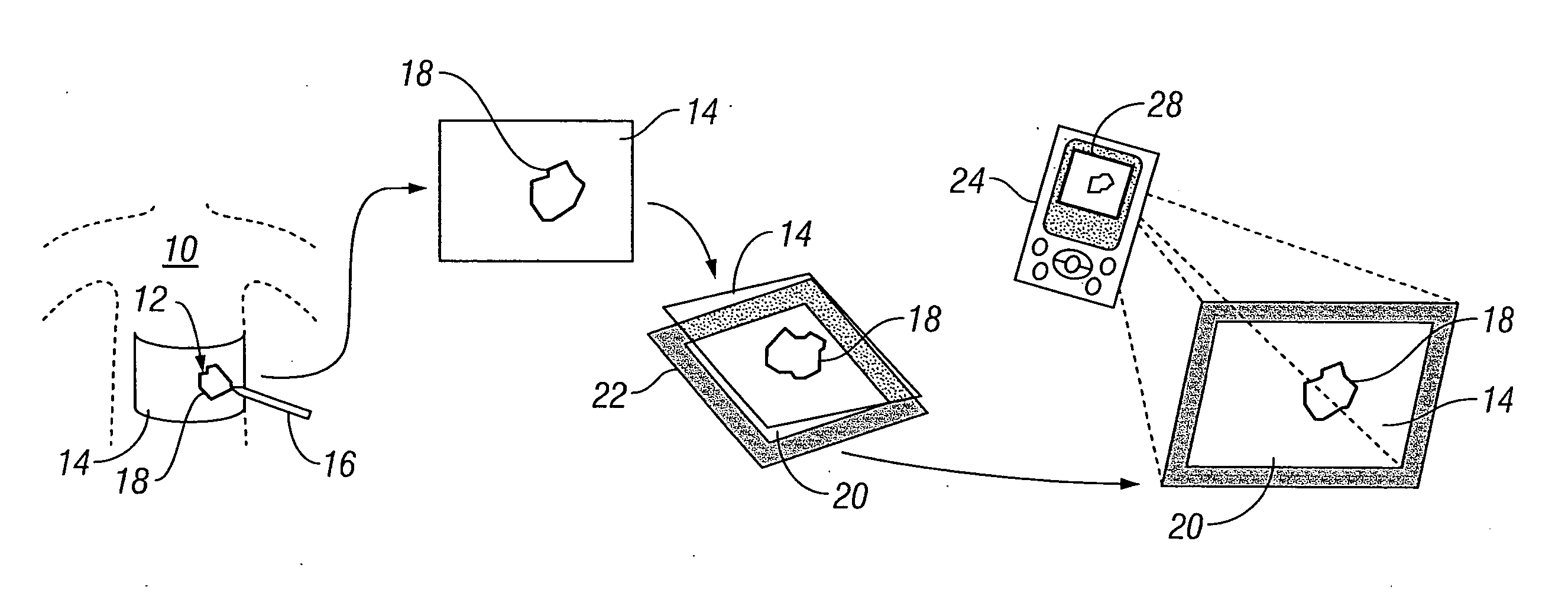
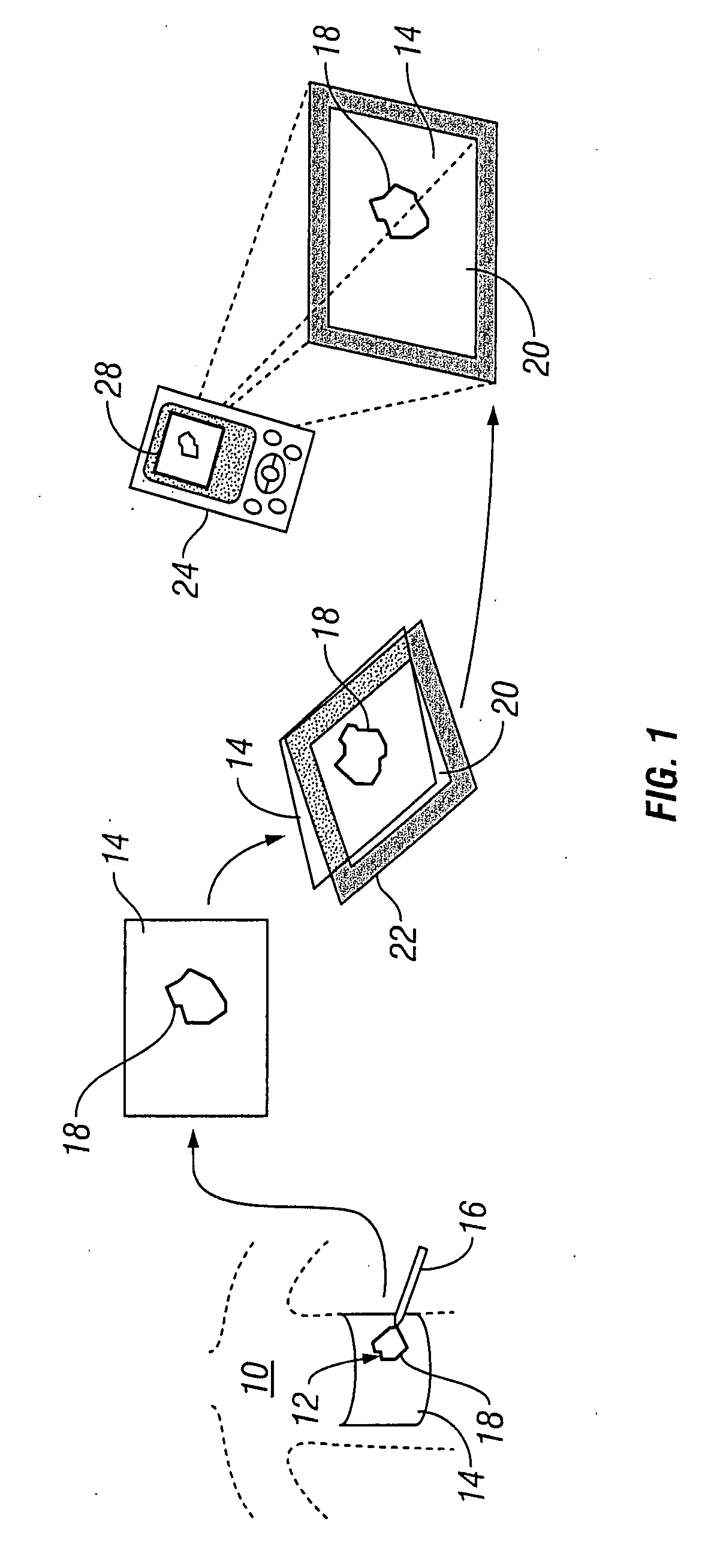
[0037] Reference is first made to FIG. 1 for a brief description of the specific components required within the system of the first preferred embodiment for implementing the methodology of the invention. In general the system involves the use of a transparent or translucent film positioned on the patient over the wound site onto which an outline trace of the wound perimeter is made with a permanent felt tip pen or the like. This transparent or translucent film bearing the wound trace is then positioned on a rectangular template frame, which in the preferred embodiment comprises a white background surrounded by a wide black band (frame). A clinician then uses a preprogrammed handheld digital processor and digital camera device (a PDA fitted with a camera, for example) to capture an image of the film / template assembly. Processing software programmed in the device identifies and quantifies the wound trace and the surrounding frame (as a reference) in order to calculate a wound area. Th...


PUM


Abstract

Systems and methods for capturing and digitizing an image of a wound and / or a wound trace from a patient and determining there from a degree of change in the characteristics of the wound. A first embodiment includes a transparent / translucent film onto which a dark outline of the wound is traced. The film is fixed to a reference template that provides a geometrically defined reference area. The film / template assembly is imaged with a digital imaging device associated with a handheld digital processor (such as a PDA). The digital image of the template and the wound trace are analyzed to identify the wound tracing and quantify the area within the closed curve. A second embodiment includes imaging the wound site with a reference tag and viewing the image on a display with an associated graphical data input device. A trace of the wound perimeter is made on display with the graphical data input device to establish a data set for the wound perimeter. The data set for the wound trace and the reference tag are analyzed to identify and quantify the wound area. In each embodiment, the system includes a display for providing both a view of the wound trace and the calculated data associated with the wound area.

Description

BACKGROUND OF THE INVENTION [0001] 1. Field of the Invention [0002] The present invention relates to generally to systems and methods for measuring a rate of biological tissue healing. The present invention relates more specifically to systems and methods for capturing, digitizing, and analyzing an image of a wound and determining there from a degree of change in the characteristics of the wound. [0003] 2. Description of the Related Art [0004] Many advances have recently been made in the field of wound therapy that have greatly increased the rate and quality of the wound healing process. Commensurate with providing an effective wound therapy regimen is the ability to make measurements of the size of the wound and the rate at which it heals. One coarse but generally effective manner of determining the rate of healing for a wound is to track changes in the overall wound size over time. [0005] Previous efforts to measure and track changes in the size of a wound have failed in many resp...

Claims


Application Information

Patent Timeline
Patent Type & Authority Applications(United States)
IPC IPC(8): A61F15/00
CPCA61B5/445A61B5/107G03B1/00A61F15/00
Inventor XU, TIANNINGJAEB, JONATHAN PAUL
Owner KCI LICENSING INC
Why Eureka
Try Eureka