Tool for an Industrial Robot

a robot and industrial technology, applied in the direction of electric programme control, dynamo-electric converter control, program control, etc., can solve the problems of complex functions, affecting the efficiency of industrial robots, and requiring process media, etc., to speed up the speed of changes, quick and simple, and quick and simple

Inactive Publication Date: 2007-11-29
ABB RES LTD
View PDF11 Cites 287 Cited by
  • Summary
  • Abstract
  • Description
  • Claims
  • Application Information

AI Technical Summary

Benefits of technology

[0011] The principal advantage of the invention is that the compact nature of the preferred embodiment with a contactless power supply and wireless communication to the tool means that a tool may be fixed to or changed on the robot or more quickly and simply. No communication connections or electrical power cables need to be disconnected or re-connected in order to change from one tool to another. There are no electrical cables running between the robot and tool to be damaged or get in the way of a tool change, especially an automatic tool change carried out by the robot. The robot simply moves the present tool to a storage position (a rack or holder or the like), releases the present tool by, for example, activating an actuator, then moves the robot arm and the tool holder on the arm to the correct position to engage a second tool at a second position, and engages the second tool, by for example, activating a locking device to fasten the tool to the tool holder. Automatic tool changes from one tool to another may be carried out swiftly and accurately. This also leads to the benefit that tool changes without physical human intervention becomes much more feasible, speeding up changes or reducing downtime and eliminating the need for a person to enter the production cell or other area around a robot. Another benefit is that automatic tool changes take place over a predictable and consistent period of time, thus reducing quality variation due to heating or cooling effects on materials used, eg adhesive, sealant, paint, or on the work object itself.
[0012] Another advantage is that by arranging the power transmitting part on the industrial robot and the receiving part on the tool the additional weight to the manipulator or robot arm is kept very small or is even less than the weight of a traditional system with cables or involving slip rings. Also the longitudinal extension of the tool interface is kept smaller than traditional solutions.
[0013] Another further advantage is that the compact size and low weight of the receiver and power supply components according to the invention reduces the wear and increases the service life for the robot or manipulator arm. In particular, wear and consequent replacement of wires, cable hoses etc running between the robot wrist and the tool is eliminated, and the invention thus reduces down time and service time. It is also an advantage that the tool according to the invention with wireless communication and contactless power may be used with any already installed robot, manipulator or similar automation device and as such may be applied to existing installations as well as new installations.

Problems solved by technology

Others may have more complicated functions and require process media, such as compressed air, cooling media, electric power as well as control signaling between the robot control unit and the tool.
However, whether arranged outside or inside a robot arm, the fact is that due to complex twisting and repeated bending of the cabling the individual cable parts of the cabling wear out frequently or begin to fail in one way or another.
However, if wireless or contactless supplies are used for power supply then the robot application may require two parallel supply arrangements to realize general and safe actuator power supply, which is made difficult and costly due to the restricted space available, for example, on a robot wrist, as well as restrictions to do with electromagnetic interference.
However robots are complex, expensive and it is very time-consuming to program them for new operations.
However, tool changes are time-consuming, cause production delays and may introduce undesirable variation into task cycles causing for example, variable heating or cooling effects.

Method used


Image

  • Tool for an Industrial Robot
  • Tool for an Industrial Robot
  • Tool for an Industrial Robot

Examples


Embodiment Construction

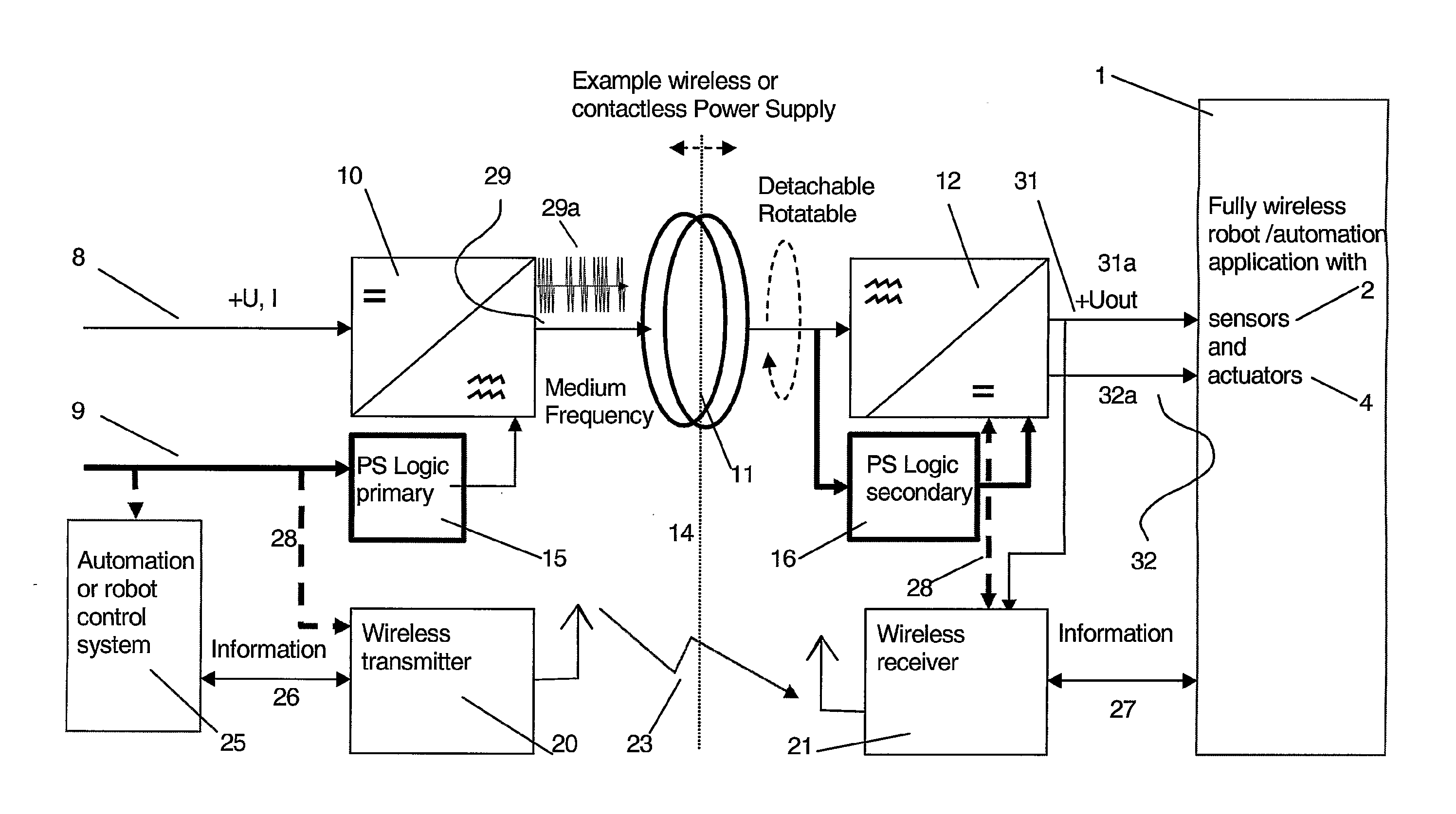
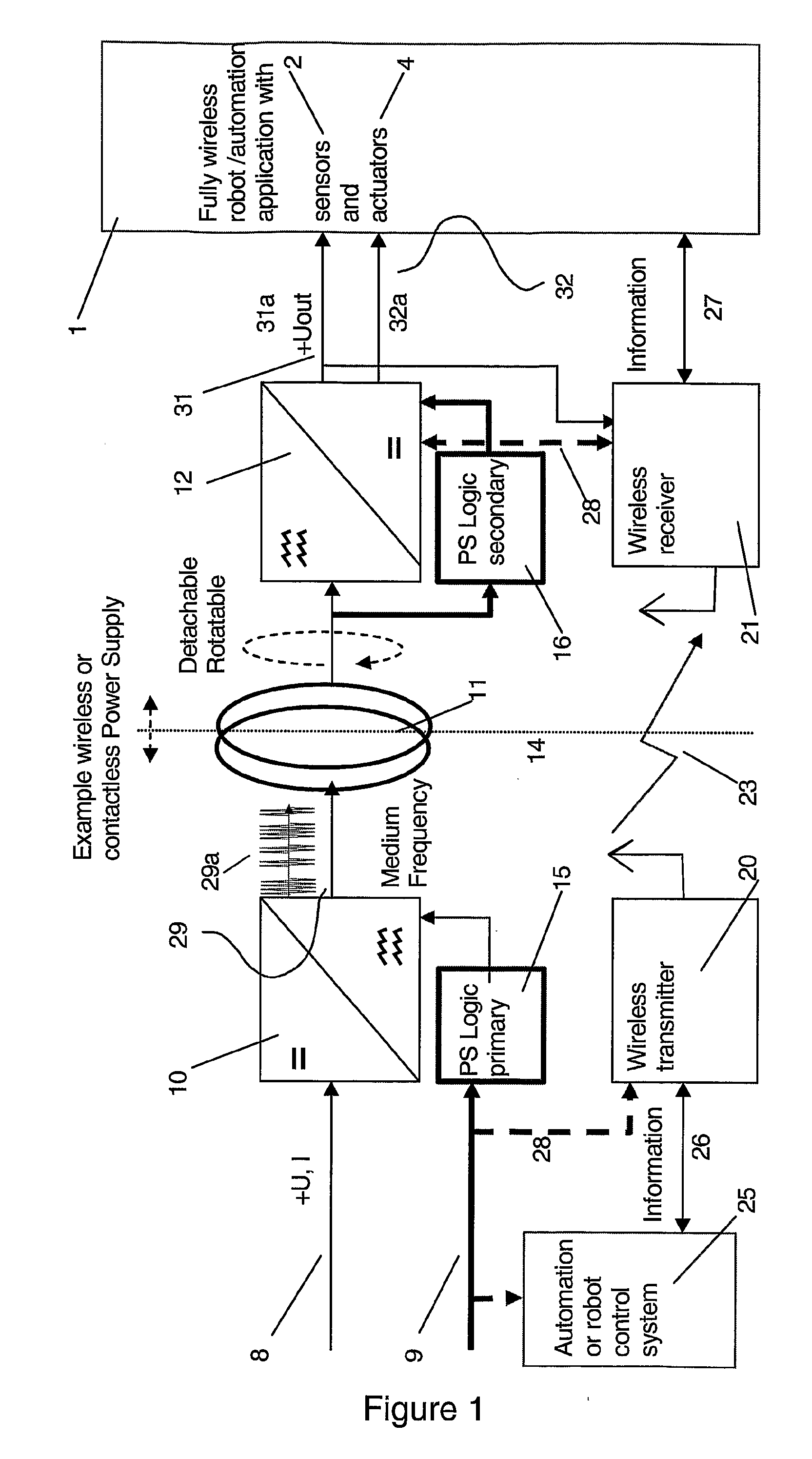
[0022]FIG. 1 shows a wireless communication system for automation or robotic automation in an embodiment of the invention in which the power supply is a wireless or contactless power supply system using e.g. magnetic or electric coupling through the air. As shown in the figure, the power supply may also be arranged with logic circuits on the sending unit and receiving unit, by which it can communicate over the power supply in a secure way. This is advantageous but the invention may also be practiced using a contactless power supply that does not include overlaid signals.

[0023] The power supply system 10 according to FIG. 1 comprises a primary part 10 and a secondary part 12. The primary part is attached to the industrial robot or other automation arrangement and the secondary part is attached to the tool. FIG. 1 shows an example of a tool or other robot application 1 that comprises one or more actuators 2 and sensors 4 (not shown in detail in FIG. 1). A contactless power supply 10 ...


PUM

PropertyMeasurementUnit
frequencyaaaaaaaaaa
frequencyaaaaaaaaaa
frequenciesaaaaaaaaaa

Abstract

A robot or manipulator including a wireless power supply and a wireless communication device. One or more actuators on the robot tool may be wirelessly powered and wirelessly controlled. The robot tool may have one or more wireless communication members for transmission of data from sensors on the tool. The power supply includes a primary power supply member and secondary power supply member. Tool changes may be carried out automatically by the robot. In other aspects of the invention a method, a control system and a computer program for carrying out the method are described.

Description

TECHNICAL FIELD [0001] The present invention concerns a tool for an industrial robot and use of the industrial robot with the tool. The invention relates to a tool for robotic and highly automated production applications comprising a contactless power supply and arranged with wireless communication to the tool. BACKGROUND ART [0002] Many different types of tools exist for use in operations carried out by robots. Common among robot tools are grippers, clamps, jaws, and more specialised tools such as paint spray guns and welding guns. Such tools may be mounted on the last axis of the manipulator or robot (eg in / on the wrist of a robot arm). Ideally, the tool should have an unlimited degree of freedom, including that it may rotate without limitations. Many tools are simple and require only a compressed air supply, for example. Others may have more complicated functions and require process media, such as compressed air, cooling media, electric power as well as control signaling between ...

Claims


Application Information

Patent Timeline
Patent Type & Authority Applications(United States)
IPC IPC(8): G05B19/418B25J9/02G06F9/00H02J17/00B25JB25J9/16B25J13/00B25J19/00G05B19/414H01F38/14
CPCG05B2219/33203B25J19/0025B25J19/0045
Inventor KJELLSSON, JIMMYBRYNE, GISLESCHEIBLE, GUNTRAMFREY, JAN-ERIKSTRAND, MARTINGENTZELL, TOBIAS
Owner ABB RES LTD
Why Eureka
Try Eureka