Plant and method for vacuum distillation of hydrocarbon liquids

a technology of hydrocarbon liquid and vacuum distillation, which is applied in vacuum distillation, vacuum distillation separation, separation processes, etc., can solve the problems of low design backpressure in the primary ejector, the primary ejector is not typically designed to take advantage, and the suction pressure of the ejector cannot be measured, so as to reduce the pressure of the vacuum distillation column and increase the operating flexibility. , the effect of reducing the pressure of the vacuum column

Inactive Publication Date: 2007-12-06
CHEVROU USA INC
View PDF5 Cites 13 Cited by
  • Summary
  • Abstract
  • Description
  • Claims
  • Application Information

AI Technical Summary

Benefits of technology

[0009] The present invention is directed to a plant and method for vacuum distillation of a liquid comprising a vacuum distillation column having a pipeline for receiving a heated feed, a gaseous vapor discharge pipeline and at least one liquid discharge pipeline for discharging at least one liquid fraction; a first condenser; a primary vacuum producing ejector having an inlet and connected to the gaseous vapor discharge pipeline and an outlet end connected to the first condenser; an auxiliary vacuum producing ejector having an inlet end connected to the gaseous vapor discharge pipeline and an outlet end connected to the first condenser; at least one second stage vacuum producing ejector having an inlet end that can be connected to various process components such as the first condenser, a separate second condenser, a condensate collection vessel or a discharge pipeline that routes distillation product to other refining systems. In a preferred embodiment two or more second stage ejectors and condensers are connected in series to form condensate product that is discharged to a condensate collection vessel, usually termed a seal drum. The auxiliary ejector, herein denoted a winter ejector, as a capacity of about 2.0 percent to 20 percent of the capacity of the primary ejector, preferably a capacity of about 5 percent to 15 percent of the primary ejector capacity and more preferably about 10 percent of the primary ejector capacity. More than one auxiliary ejector can be installed to increase operating flexibility; for example, if a 10 percent load reduction is desired two 5 percent auxiliary ejectors may be installed in parallel with a primary ejector. The winter ejector(s) is / are operated in parallel with the primary ejector during the cool season months when the average temperature of available cooling water, for example, in the US Gulf coast region is about 70° F. or about 15 degrees lower than average cooling water temperatures available during the warm season months. In other regions of the World, ambient, temperatures and cooling water temperature will vary significantly from this US Gulf Coast region example. The operative factors are the relative difference between cool season and warm season cooling water temperatures and the design limits of the primary ejector. When the winter ejector is operated, the load to the primary ejector will decrease resulting in decreased pressure to the vacuum distillation column. Generally, a decrease in load to the primary ejector will result in an equivalent decrease in vacuum column pressure. For example, if a 10 percent decrease in load to the primary ejector is achieved, the corresponding column pressure will also be reduced 10 percent. Such cool season reduction in vacuum column pressure will increase the recovery of heavy gas oil from heavy petroleum hydrocarbon feeds.

Problems solved by technology

This extra condensing capacity results in a lower than design backpressure in the primary ejector.
Thus, the primary ejector is not typically designed to take advantage of lower backpressures available as a result of lower temperature cooling waters available during the cooler season months.
Under this circumstances lowering the backpressure will not have any measurable effect on the ejectors suction pressure.
Available methods to reduce the column pressure, such as decreasing the suction load by decreasing the column stripping steam injection rate or reducing the furnace lift steam injection rate, has the effect of decreasing efficiency of the vacuum column and reduces the recovery of desirable gas oil product.
Installation of such systems would, of course, involve undesirable capital expenditure.

Method used


Image

  • Plant and method for vacuum distillation of hydrocarbon liquids
  • Plant and method for vacuum distillation of hydrocarbon liquids
  • Plant and method for vacuum distillation of hydrocarbon liquids

Examples


Embodiment Construction

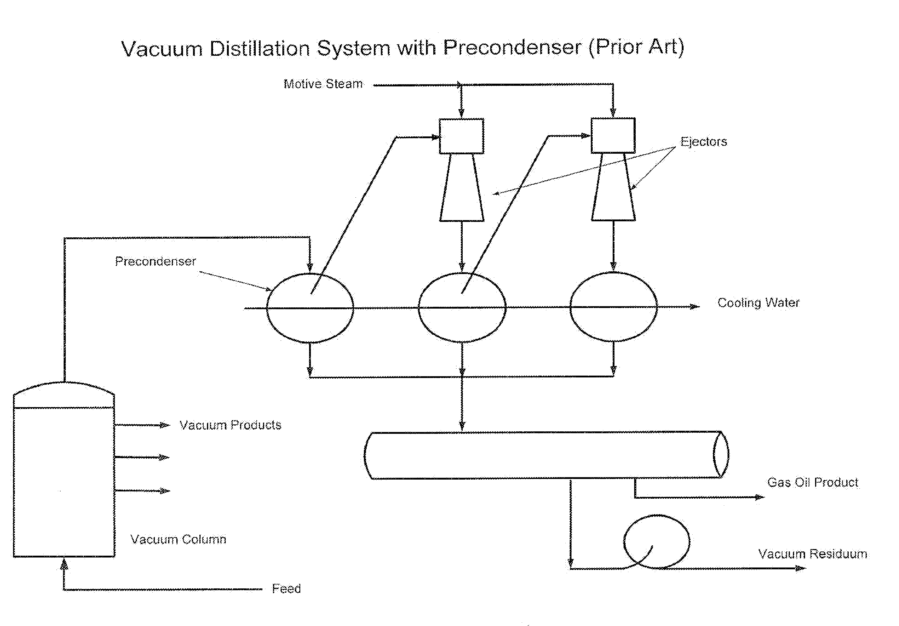
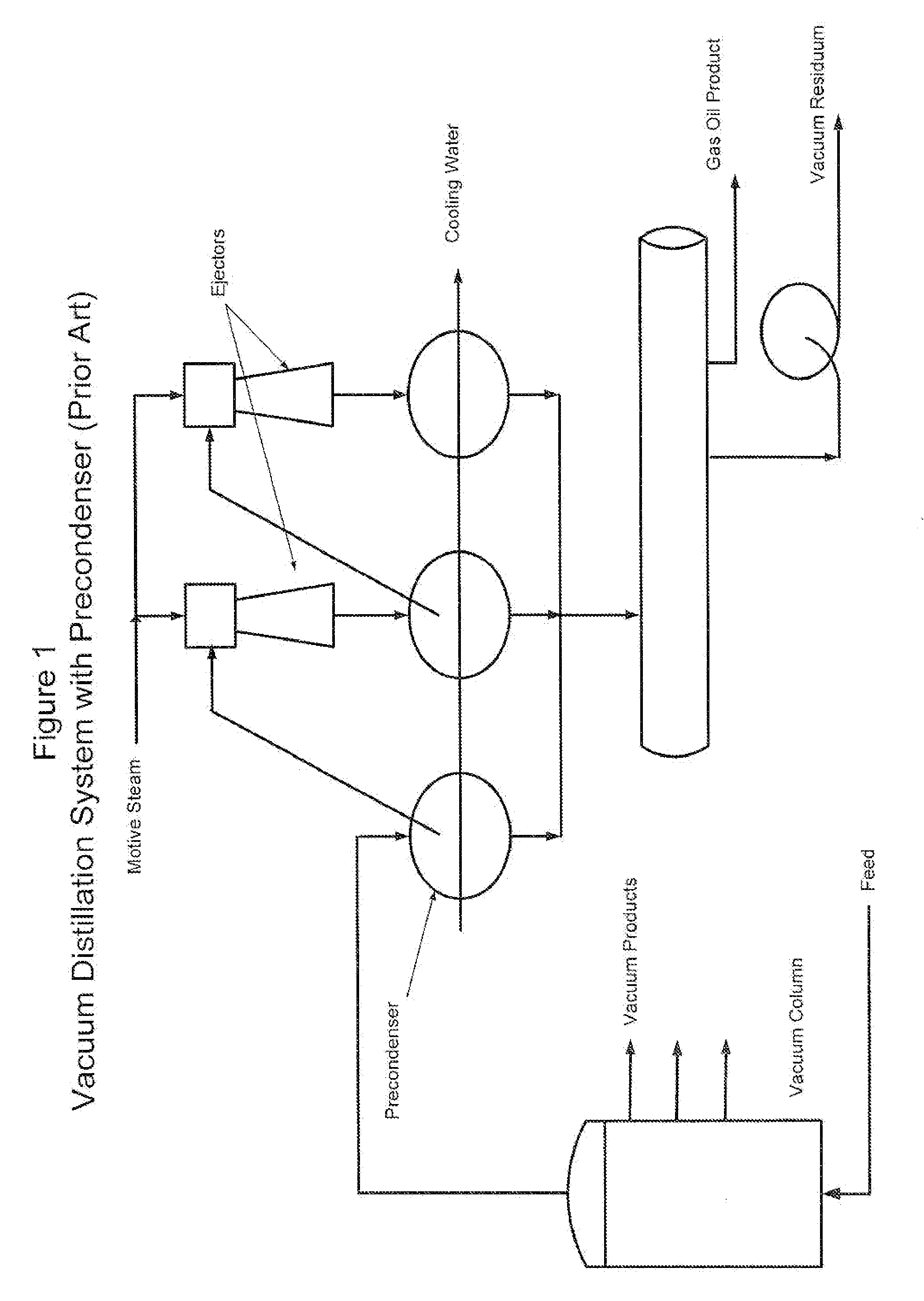
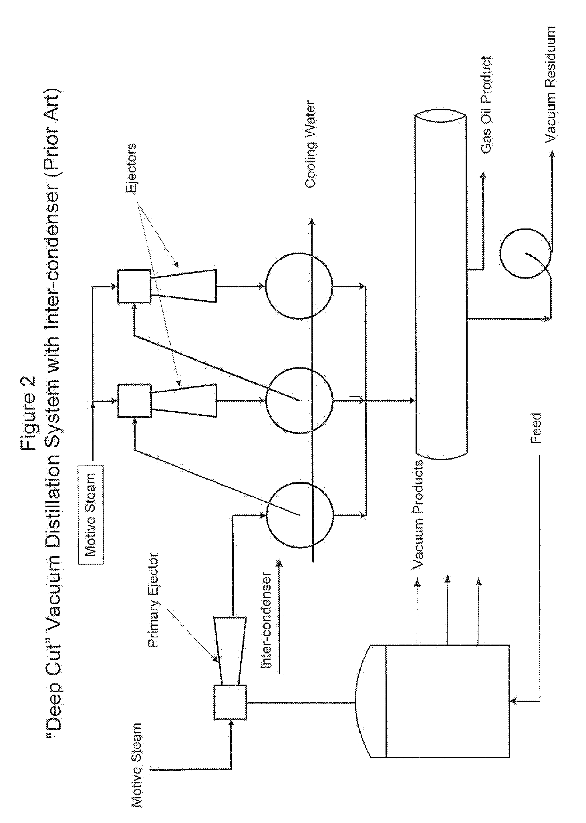
[0011] Refer to FIG. 5. A system for vacuum distillation of a hydrocarbon liquid, comprises a vacuum distillation column 10, a pipeline for receiving a heated feed 20, a gaseous vapor discharge pipeline 30, at least one liquid discharge pipeline 40, a first condenser 45, a primary vacuum producing ejector 50 having an inlet end 50A and an outlet end 50B, connected to the first condenser 46 via pipeline 60, and auxiliary vacuum producing ejector 70 having an inlet end 70A connected to the gaseous vapor discharge pipeline 30 and outlet end connected to the first condenser 45, either via pipeline 50C in one embodiment or directly in an alternative embodiment. The system further comprises at least one-second stage vacuum producing ejector 800 having an inlet end connected to the first condenser 45 via pipeline 90 and an outlet end connected to at least one-second condenser 100 via pipeline 110. Preferably, the system includes at least two-second stage vacuum producing ejectors 80, 81 an...


PUM

PropertyMeasurementUnit
temperatureaaaaaaaaaa
pressureaaaaaaaaaa
pressureaaaaaaaaaa

Abstract

A vacuum distillation system and method utilizing an auxiliary, low capacity vacuum producing ejector operated in parallel with a primary ejector during the winter months enables significant reduction in the absolute pressure of a vacuum distillation column. Operation of a vacuum distillation tower at lower absolute pressures results in increased yield of desirable vacuum distillation products.

Description

CROSS-REFERENCED AND RELATED APPLICATIONS [0001] This application is a divisional application of U.S. patent application Ser. No. 10 / 401,617 filed in the United States Patent and Trademark Office on Mar. 26, 2003. Said U.S. patent application Ser. No. 10 / 401,617 is, in its entirety, incorporated into this application by reference.FIELD OF THE INVENTION [0002] The present invention relates to the field of hydrocarbon refining by the method of vacuum distillation. BACKGROUND OF THE INVENTION [0003] Vacuum distillation of petroleum hydrocarbons is a well known refining process commonly utilized in the art to minimize thermal cracking of heavier fractions of crude oil and obtain lighter desired products. Di-stilling these heavier materials under vacuum, that is lower pressure, decreases the boiling temperature of the various hydrocarbon fractions in the feed and therefore minimizes thermal cracking of these fractions. In conventional vacuum distillation systems, distillation is carried ...

Claims


Application Information

Patent Timeline
Patent Type & Authority Applications(United States)
IPC IPC(8): B01D3/10C10G7/06
CPCB01D3/10Y10S203/16C10G7/06
Inventor MUSIAL, THOMAS HUGH
Owner CHEVROU USA INC
Why Eureka
Try Eureka