Storage battery system, on-vehicle power supply system, vehicle and method for charging storage battery system

a storage battery and battery technology, applied in the direction of propulsion parts, engine-driven generators, climate sustainability, etc., can solve the problems of small electric capacity, inability to compact, and inconvenient charging, so as to achieve efficient charging and long-term discharge

Active Publication Date: 2007-12-13
KK TOSHIBA
View PDF21 Cites 193 Cited by
  • Summary
  • Abstract
  • Description
  • Claims
  • Application Information

AI Technical Summary

Benefits of technology

[0010]It is an object of the invention to provide a long-life storage battery system capable of efficient charging during fast charging, such as regenerative charging, and capable of discharging for a long time during a low-load operation, and also to provide an on-vehicle power supply system and vehicle provided with such a storage battery system, and a charging method for such a storage battery system.

Problems solved by technology

However, nickel hydride batteries installed in hybrid vehicles, for example, have the problem that they suddenly generate heat during high-power outputting or fast charging (regenerative charging), and their thermal degradation is very conspicuous.
Furthermore, lead storage batteries used as emergency power supplies have a low weight energy density and hence heavy weight, therefore, involve constraints on their installation place.
Compared to secondary batteries, capacitors can accumulate high power instantly, but have a very small electric capacity and hence cannot be made compact.
Accordingly, their cycle lives will degrade if fast charging, such as energy regeneration, is performed.
This being so, when low power is input to the batteries, they cannot efficiently accumulate regenerative energy.
Further, if lithium ion batteries are made into high-power ones, their inherent high energy density is significantly reduced to thereby reduce their discharge capacity.
However, it is difficult to satisfy both the enhancement of energy regenerative performance and acceleration performance, and the traveling performance during motor driving (EV driving).
However, in this storage battery system, the active material of the negative electrode is low in the rate of occluding and discharging ions, and hence efficient charging cannot be achieved during fast charging, such as regenerative charging.

Method used


Image

  • Storage battery system, on-vehicle power supply system, vehicle and method for charging storage battery system
  • Storage battery system, on-vehicle power supply system, vehicle and method for charging storage battery system
  • Storage battery system, on-vehicle power supply system, vehicle and method for charging storage battery system

Examples


first embodiment

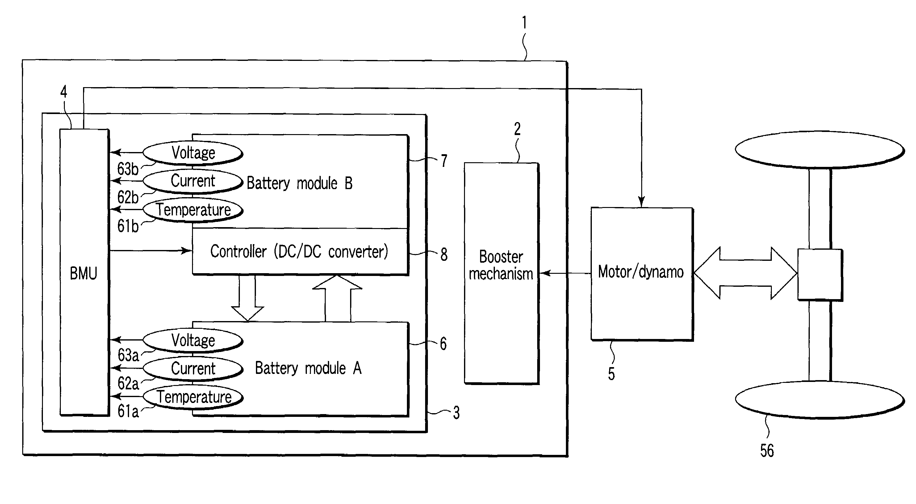
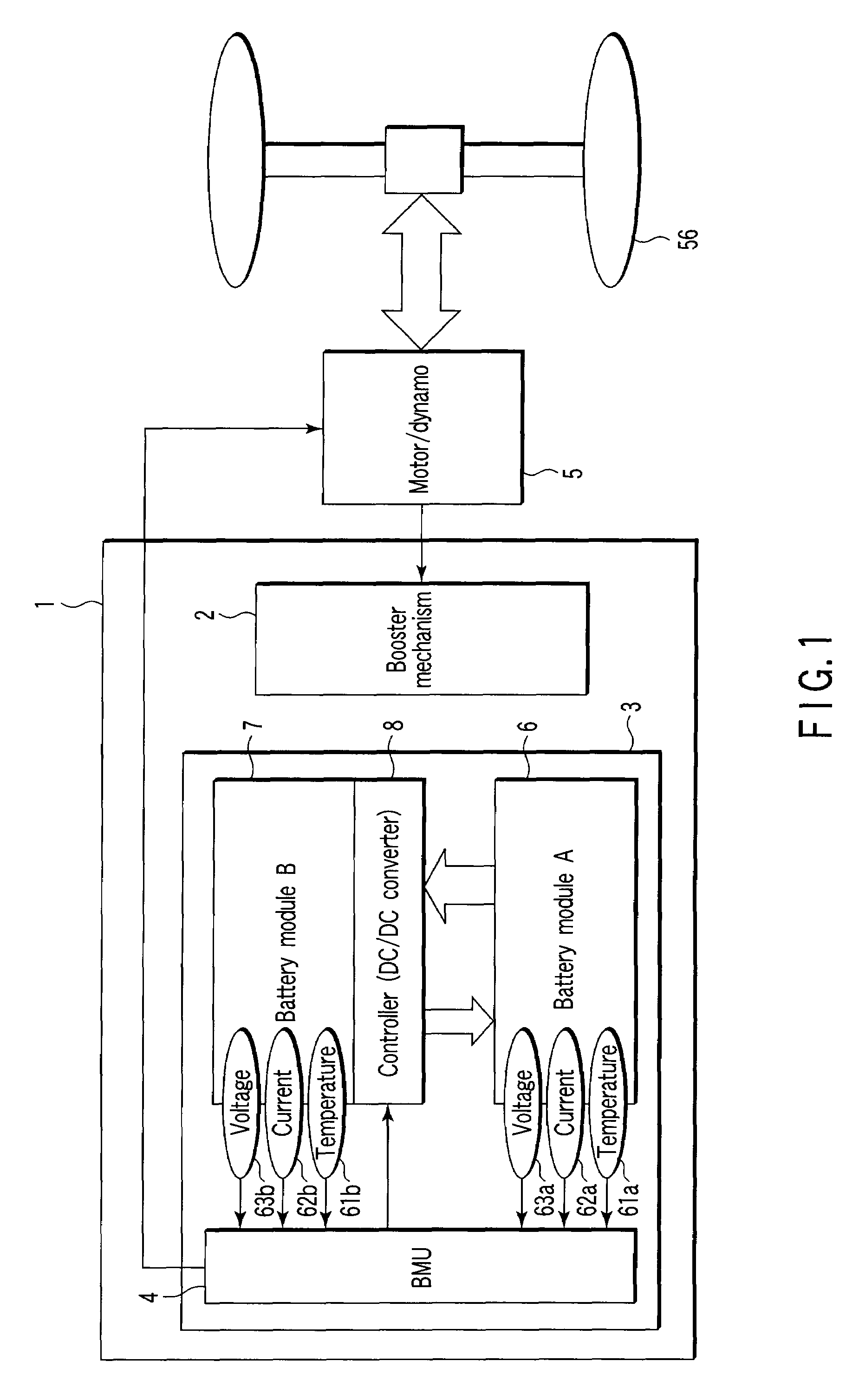
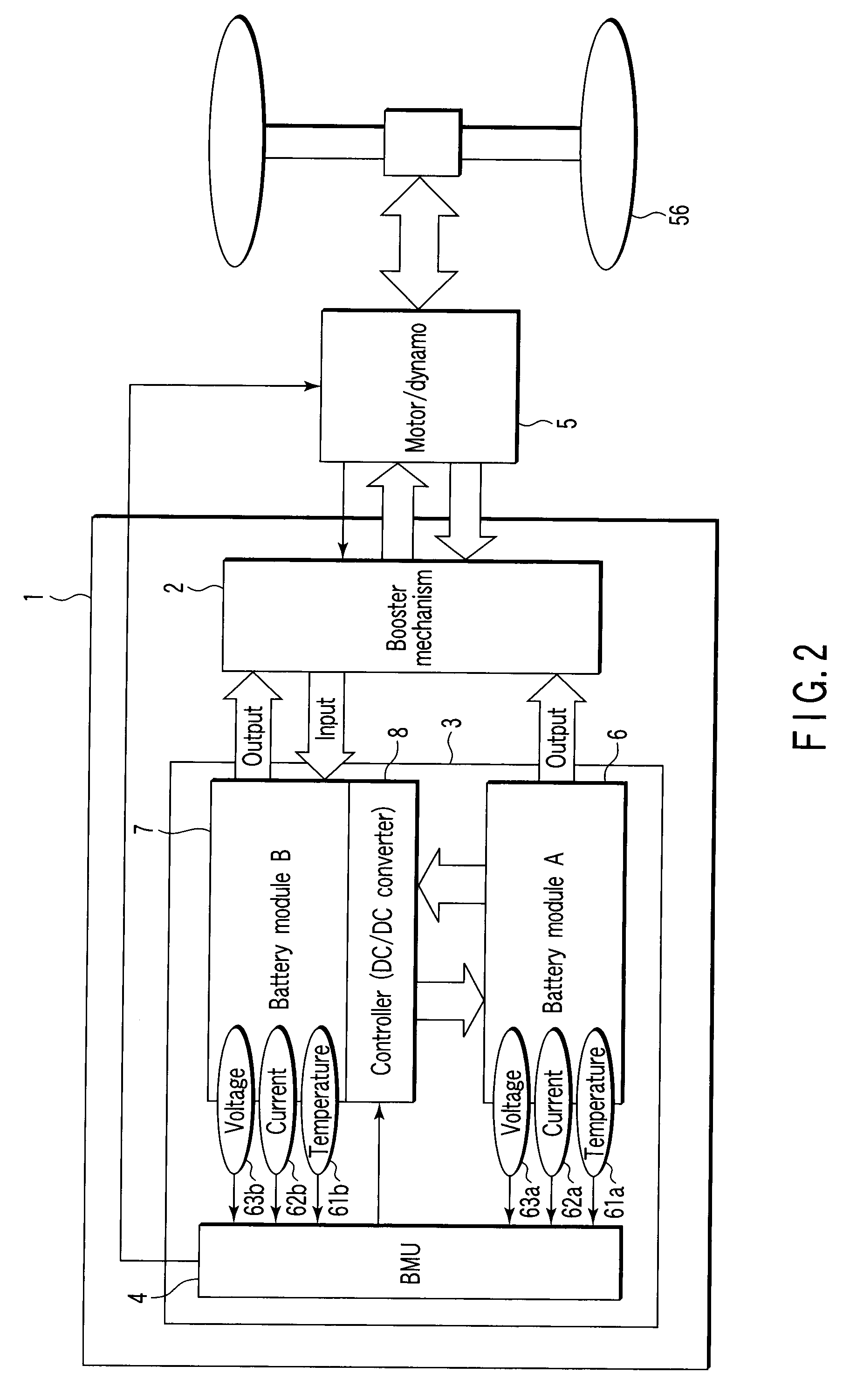
[0046]As shown in FIGS. 1 and 2, the storage battery system 1 of the first embodiment comprises a booster mechanism 2, battery modules A and B connected to the booster mechanism 2, and a battery control unit (BMU) 4 connected to the battery modules A and B. The battery module B has a module, in which a plurality of single cells formed of thin nonaqueous electrolyte secondary batteries 7 are connected parallel to each other or in series. The battery module A is intermittently connected to the battery module B parallel to each other via a controller 8, and controls the amounts of current input to and output from the battery module B. The controller B contains a DC / DC converter, and performs constant voltage control to enable power to be supplied from the battery module A to the battery module B.

[0047]FIG. 3 shows an example of a unit cell 21 as a nonaqueous electrolyte battery. An electrode group 11 has a flat, spiral structure formed of a positive electrode 12, negative electrode 13 ...

second embodiment

[0117]The storage battery system of the first embodiment is suitable for rapid charging and discharging, as well as for charging using regenerative power. Examples of this use are a power supply for digital cameras, a power supply for light vehicles such as assist bicycles, a backup power supply (uninterruptible power supply devices) for personal computers or for use in factories, and a cleaner.

[0118]A storage battery system according to a second embodiment can be made to the same structure as that of the system of the first embodiment, except for regenerative power is not used for charging. It is preferable to set the charging rate to a range of 2 C or more and 120 C or less. Incidentally, “1 C” is a current required for each unit cell to be completely discharged within an hour. For convenience, the nominal capacitance of each unit cell can be replaced with 1 C.

[0119]In the storage battery systems of the first and second embodiments, a battery pack containing, in a single case, the...

example 1

[0134]A description will be given of a method for producing the negative electrode of a second nonaqueous electrolyte battery 7 included in the battery module B. Lithium titanate (Li4Ti5O12) with an average grain size of 0.3 μm, as an active material, carbon powder with an average grain size of 0.4 μm, as a conductive agent, and polyvinylidene fluoride (PVdF) as a binding agent were mixed with a weight ratio of 90:7:3 in n-methylpyrrolidone (NMP) solvent, thereby preparing slurry. The slurry was coated on aluminum alloy foil (purity: 99.4%) with a thickness of 12 μm and an average crystal grain size of 50 μm, and the resultant structure was dried and pressed to thereby prepare a negative electrode with an electrode density of 2.4 g / cm3. The negative collector was prepared by annealing, at 200° C., aluminum alloy foil (purity: 99.4%) with a thickness of 12 μm and an average crystal grain size of 90 μm, and then cooling the resultant structure to room temperature.

[0135]A method for pr...


PUM

PropertyMeasurementUnit
grain sizeaaaaaaaaaa
electrical potentialaaaaaaaaaa

Abstract

A storage battery system includes a battery module A with a first nonaqueous electrolyte battery including a negative-electrode material which has an average grain size of 2 μm or more and is used to occlude and discharge lithium ions, a battery module B with a second nonaqueous electrolyte battery set at a lithium-ion-occluding potential of 0.4V (vs.Li/Li) or more, and including a negative-electrode material which has an average grain size of primary particles of 1 μm or less and is used to occlude lithium ions, and a controller configured to intermittently connect the module A to the module B to intermittently supply power from the module A to the module B to set a charge state and a discharge depth of the second nonaqueous electrolyte battery within a range of 10 to 90%, when no power is supplied to the module B at least from an outside.

Description

CROSS-REFERENCE TO RELATED APPLICATIONS[0001]This application is based upon and claims the benefit of priority from prior Japanese Patent Application No. 2006-163668, filed Jun. 13, 2006, the entire contents of which are incorporated herein by reference.BACKGROUND OF THE INVENTION[0002]1. Field of the Invention[0003]The present invention relates to a storage battery system suitable for, for example, vehicles, bicycles, trams, elevators, aerogenerators and emergency power supplies, etc., which aim to enhance energy efficiency, and also relates to an on-vehicle power supply system and vehicle provided with such a storage battery system.[0004]2. Description of the Related Art[0005]In recent years, hybrid vehicles, bicycles, trams, elevators and aerogenerators, etc., which is provided with a battery, have been proposed, and some of them have been put into practice, to effectively use energy, in particular, regenerative energy as environmental measures. Secondary batteries, which have be...

Claims


Application Information

Patent Timeline
Patent Type & Authority Applications(United States)
IPC IPC(8): B60K1/04B60L50/15B60L50/16H01M4/02H01M4/485H01M4/587H01M10/05H01M10/44H01M50/204H02J7/00H02J7/02H02J7/14
CPCB60K6/46Y02T90/121B60L11/14B60L11/185B60L11/1868B60L11/187B60L11/1879B60W10/08B60W20/00B60W2510/244B60W2510/246H01M2/1077H01M4/485H01M4/587H01M10/0525H01M10/441H01M10/46H01M16/00H01M2004/021H02J7/1423Y02E60/122Y02T10/6217Y02T10/6269Y02T10/7005Y02T10/7011Y02T10/7066Y02T10/7077Y02T90/128Y02T90/14B60L2200/26B60L11/123Y02T10/7072B60L50/61B60L50/16B60L53/11B60L58/20B60L58/24B60L50/64Y02E60/10Y02T10/62Y02T10/70H01M50/204B60W10/26Y02T90/12
Inventor TAKAMI, NORIOINAGAKI, HIROKITATEBAYASHI, YOSHINAO
Owner KK TOSHIBA
Why Eureka
Try Eureka