Sense amplifier circuit and sense amplifier-based flip-flop having the same

a technology of sense amplifier and sense amplifier, applied in pulse generators, instruments, pulse techniques, etc., to achieve the effect of preventing a degradation of output characteristics and reducing signal delay tim

Active Publication Date: 2007-12-13
SAMSUNG ELECTRONICS CO LTD
View PDF12 Cites 379 Cited by
  • Summary
  • Abstract
  • Description
  • Claims
  • Application Information

AI Technical Summary

Benefits of technology

[0092] According to exemplary embodiments of the present invention, a sense amplifier-based flip-flop operating in response to a clock signal includes a first latch for outputting a second logic level signal to a first output terminal pair when the clock signal has a first logic level, and outputting an evaluation signal pair corresponding to an input signal pair to the first output terminal pair when the clock signal has a second logic level; a second latch configured to latch the evaluation signal pair and to output the evaluation signal pair to a second output terminal pair; a floating preventing unit controlled by signals of the first output terminal pair and so operationally connected between current passing nodes of the first latch so as to prevent the first output terminal pair from floating; an input signal applying unit disposed between the current pass

Problems solved by technology

The sense amplifier circuit and the sense amplifier-based flip-flop may improve a decreased processing speed caused by a

Method used


Image

  • Sense amplifier circuit and sense amplifier-based flip-flop having the same
  • Sense amplifier circuit and sense amplifier-based flip-flop having the same
  • Sense amplifier circuit and sense amplifier-based flip-flop having the same

Examples


Embodiment Construction

[0119] The present invention will now be described more fully with reference to the accompanying drawings, in which exemplary embodiments of the invention are shown. This invention may, however, be embodied in may different forms and should not be construed as limited to the exemplary embodiments set forth herein. Like reference numerals denote like elements in the drawings.

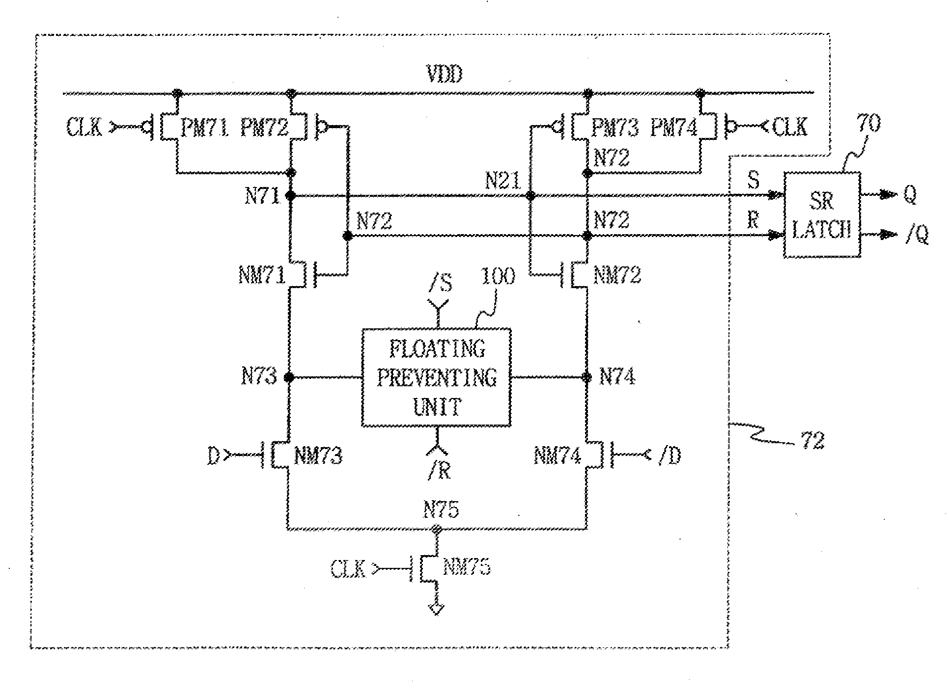
[0120]FIG. 7 is a circuit diagram of a sense amplifier-based flip-flop according to an exemplary embodiment of the present invention, and FIG. 8 is a timing diagram illustrating operation of the sense amplifier-based flip-flop of FIG. 7.

[0121] With reference to FIG. 7, the sense amplifier-based flip-flop operating in response to a clock signal CLK includes a first latch 72, a second latch 70 and a floating preventing unit 100 to prevent a floating of the output node.

[0122] The first latch 72 may include a first PMOS transistor PM71 disposed between a power terminal VDD and a first node N71, to be turned on or ...


PUM


Abstract

A sense amplifier-based flip-flop includes a first latch, a second latch, a floating reduction unit, an input signal applying unit, a ground switch and a delay reduction unit. The first latch outputs a signal to a first output terminal pair, and outputs an evaluation signal pair corresponding to an input single pair to the first output terminal pair. The second latch latches the evaluation signal pair and outputs the evaluation signal pair to a second output terminal pair. The floating reduction unit is controlled by signals of the first output terminal pair and is operationally connected between current passing nodes of the first latch to prevent the first output terminal pair from floating. The input signal applying unit is disposed between the current passing nodes and a ground terminal, and receives the input signal pair. The ground switch is disposed between the input signal applying unit and the ground terminal, and is controlled by the clock signal. The delay reduction unit is disposed between the input signal applying unit and the ground switch, and reduces a signal delay from when the clock signal to when the evaluation signal pair is output from the second output terminal pair.

Description

CROSS-REFERENCE TO RELATED APPLICATIONS [0001] This application claims priority to Korean Patent Applications Nos. 10-2006-0038633, filed on Apr. 28, 2006, and 10-2006-0053305, filed on Jun. 14, 2006, the contents of which are incorporated herein by reference in their entirety. BACKGROUND OF THE INVENTION [0002] 1. Technical Field [0003] The present disclosure relates to semiconductor integrated circuits, and more particularly, to a sense amplifier and a sense amplifier-based flip-flop having the same. [0004] 2. Discussion of Related Art [0005] Mobile devices, such as cellular telephones, personal digital assistants (PDAs) and notebook computers, have an increased power management expense based on an increasingly large capacity and increasing clock speeds. Very large scale integration (VLSI) systems benefit from lower power consumption by improving their circuit structure or logic. [0006] The circuit structure in the VLSI system may be largely divided into two functions. One functio...

Claims


Application Information

Patent Timeline
IPC IPC(8): H03K19/096
CPCG11C7/065G11C7/02
Inventor SOHN, YOUNG-SOO
Owner SAMSUNG ELECTRONICS CO LTD
Why Eureka
Try Eureka