Wind power plant

a wind power plant and wind turbine technology, applied in the direction of rotors, marine propulsion, vessel construction, etc., can solve the problems of insufficient speed limitation, easy destruction of electronic components, and insufficient torque limitation, and achieve accurate torque regulation and speed regulation

Inactive Publication Date: 2007-12-13
ROBERT BOSCH GMBH
View PDF12 Cites 22 Cited by
  • Summary
  • Abstract
  • Description
  • Claims
  • Application Information

AI Technical Summary

Benefits of technology

[0013] The asynchronous motor may be connected to the network connection via a frequency converter. The frequency converter converts the 3-phase network voltage of fixed frequency and amplitude, that is present, into a 3-phase voltage having adjustable frequency and amplitude. For instance, a U/f frequency converter, which regulates the motor voltage and the frequency in a linear ratio, can be used, or a field-oriented frequency converter can be used which regulates torque and rotar

Problems solved by technology

For safety reasons, each individual rotor blade has its own adjusting drive, so that a sufficient speed limitation is achieved even if one of the adjusting drives should fail.
It is basically required that the blade angle adjustment system be designed electrically as simply as possible, and insensitive to malfunctions, since wind power plants are greatly exposed to the danger of lightning strikes, and electronic components react in a very sensitive manner to overvoltages, and are easily destroyed.
What is disadvantageous in such wind power plants is that the mechanically commutated DC mo

Method used


Image

  • Wind power plant
  • Wind power plant

Examples


Embodiment Construction

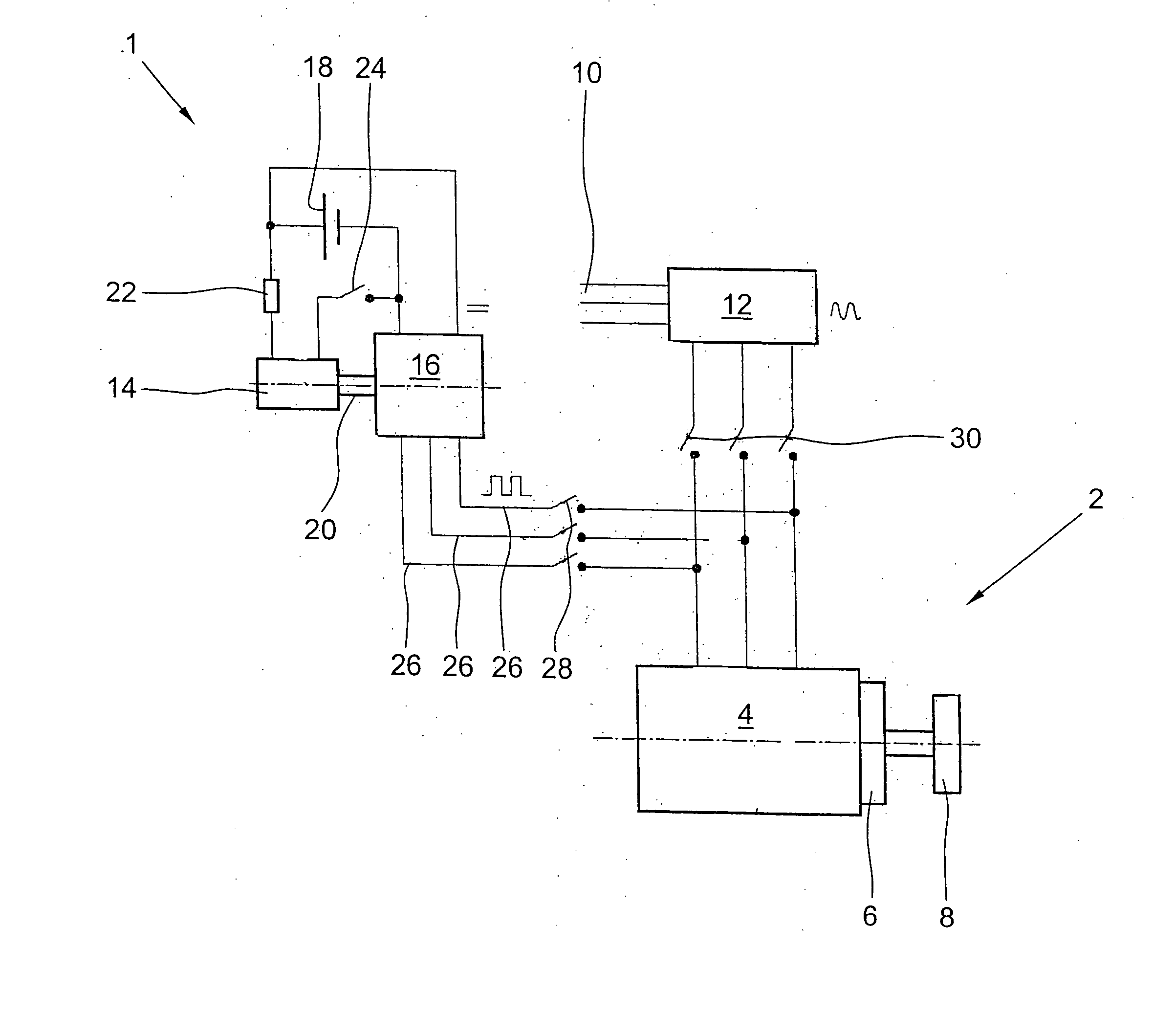
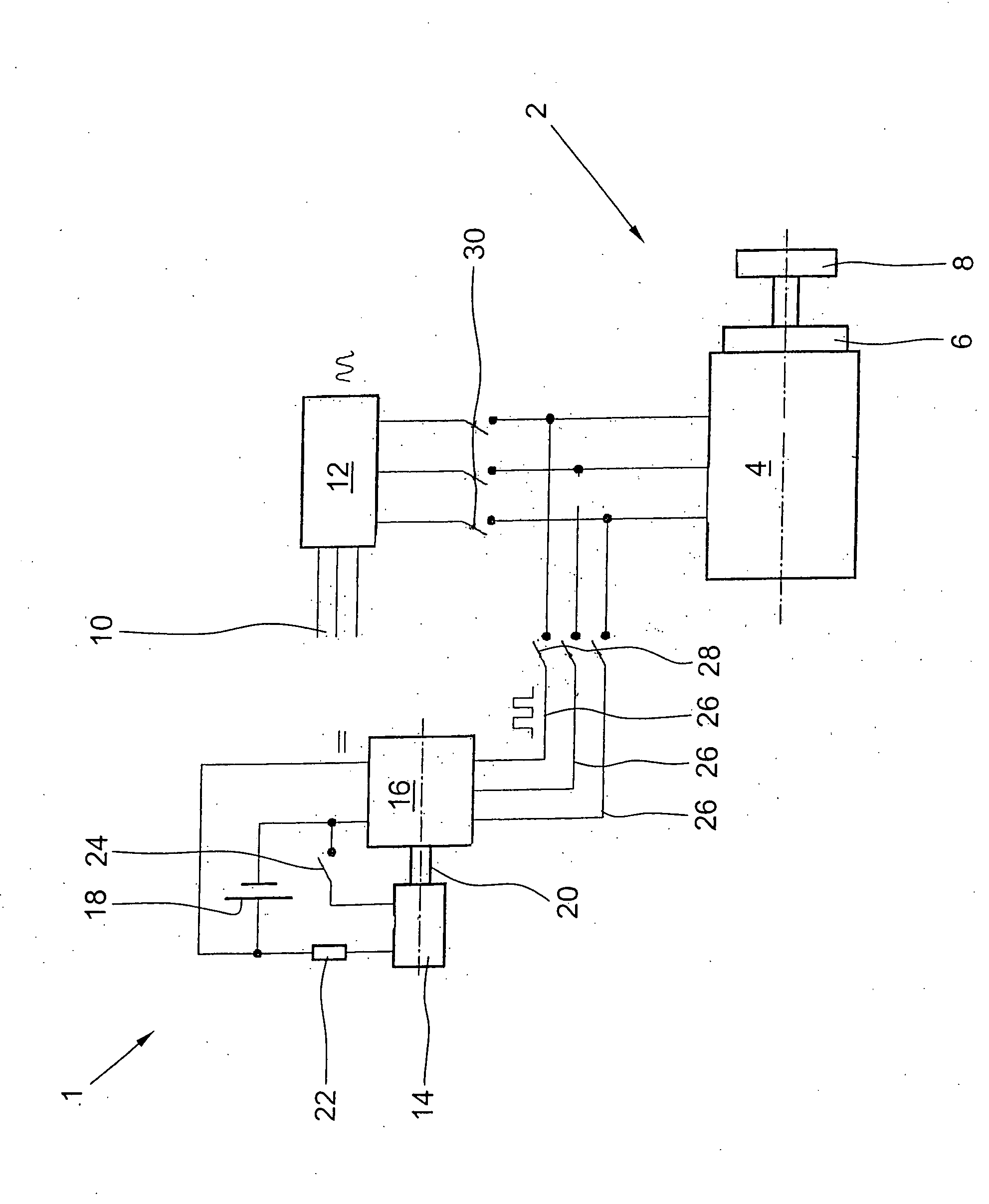
[0021] The FIGURE shows a schematic representation of a wind power plant 1 according to the exemplary embodiment and / or the exemplary method of the present invention, having a device 2 for adjusting the angle of pitch of the rotor blades (not shown) positioned rotatably on a hub. The angle of pitch of the rotor blades to the wind is able to be adjusted via blade adjustment mechanism 2, as a function of the wind force, in order to use the wind force in an optimum fashion, and to put the rotor blades into their safety position when the wind is too strong. In this way, overload damage in wind power plant 1, based on an inadmissibly high speed, is avoided. Blade adjustment mechanism 2 is made up essentially of an adjustment drive 4 which, in the exemplary embodiment shown, is executed as an asynchronous motor, and a gearing 6 preconnected to it. Thereby, even using relatively small, light asynchronous motors 4, the required high torques for the rotor adjustment can be mustered.

[0022] A...


PUM


Abstract

A wind power plant having a device for adjusting the angle of pitch of the rotor blades situated on a hub, the rotor blades being able to be set via respectively at least one asynchronous motor in normal operation, and being able to be rotated into their safety position (feathered pitch) in emergency operation. The asynchronous motor is fed in emergency operation via a commutator driven by a DC motor from a DC source that is independent of the network.

Description

FIELD OF THE INVENTION [0001] The present invention relates to a wind power plant. BACKGROUND INFORMATION [0002] In wind power plants, the flow energy of the wind over a rotor is converted to usable rotational energy. The angle of pitch of the rotor blades to the wind is set, for this purpose, via a mechanical blade adjustment mechanism as a function of the strength of the wind, in order to utilize the wind power in optimal fashion, and in order to put the rotor blades into their feathered pitch, that is, into a safety position in which the plant is braked aerodynamically (torque on main origin=0), in order to avoid overload damage to the wind power plant, caused by an inadmissibly high speed of the rotor. For safety reasons, each individual rotor blade has its own adjusting drive, so that a sufficient speed limitation is achieved even if one of the adjusting drives should fail. [0003] If there is a failure in the power supply system, since it then has to be possible to put the roto...

Claims


Application Information

Patent Timeline
IPC IPC(8): F03B3/14
CPCF03D7/0224F03D7/0268Y02E10/723Y02E10/721F05B2260/76Y02E10/72
Inventor DANTLGRABER, JOERG
Owner ROBERT BOSCH GMBH
Why Eureka
Try Eureka