Directed-flow assay device

Active Publication Date: 2007-12-13
QUANTUM DESIGN
View PDF40 Cites 16 Cited by
  • Summary
  • Abstract
  • Description
  • Claims
  • Application Information

AI Technical Summary

Benefits of technology

[0027]The present invention has improved sensitivity over known lateral flow devices. It provides a very rapid (within a few minutes) analytical measurement. There are many advantages of using magnetic particles over known colored particles or other optical indicators in the prior art. These include quantitative linearity of magnetic detection with respect to the amount of magnetic material present over a wide range, through at least four orders of magnitude. Time stability is also superior because magnetic particles are stable, thereby allowing the developed assay to be archived and retested as necessary. Further, magnetic particles are generally inert to biological systems and to the environment. So they not only remain stable, they are environmentally and biologically safe. Further, magnetic particles are already in widespread use with other technologies throughout the diagnostics industry so they are readily available. Other benefits of magnetic detection are that since the particles are superparamagnetic, they are magnetic only when exposed to a magnetic field. This allows them to be freely manipulated in solutio

Problems solved by technology

Although useful, currently available chromatographic techniques using test strips have a number of drawbacks.
Some samples, for example, fecal samples, contain particulate matter that can obscure or color the pores of the chromatographic medium, greatly hindering detection of the labeling reagents.
Blood for example, obviously contain cells and colored components that obscure the color generation in the test, and therefore make it difficult, if not impossible, to read.
Blood cells also tend to clog the pores in the medium.
Wet chromatographic medium is also sometimes difficult to read because of specular reflection from the chromatography medium.
There are various other drawbacks to chromatographic techniques, including physical properties of lateral flow, fluid front movement along the strip, and color generation intensity and location.
The available forms of lateral flow devices have a large portion of their components that are only used for mechanical support of the chromatographic membrane, and

Method used


Image

  • Directed-flow assay device
  • Directed-flow assay device
  • Directed-flow assay device

Examples


Embodiment Construction

[0038]In the following description of preferred embodiments, reference is made to the accompanying drawings, which form a part hereof, and which show by way of illustration, specific embodiments of the invention. It is to be understood by those of working skill in this technological field that other embodiments may be utilized, and structural, as well as procedural changes may be made without departing from the scope of the present invention.

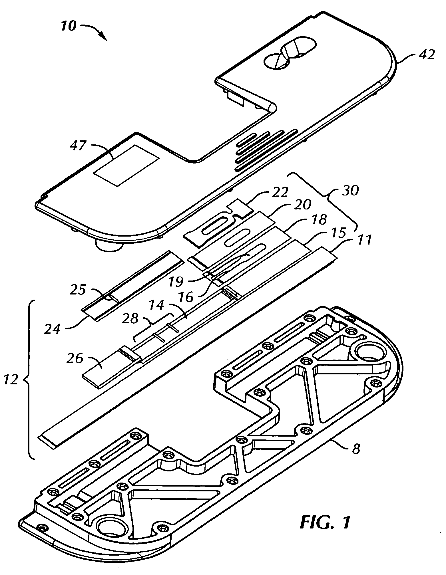
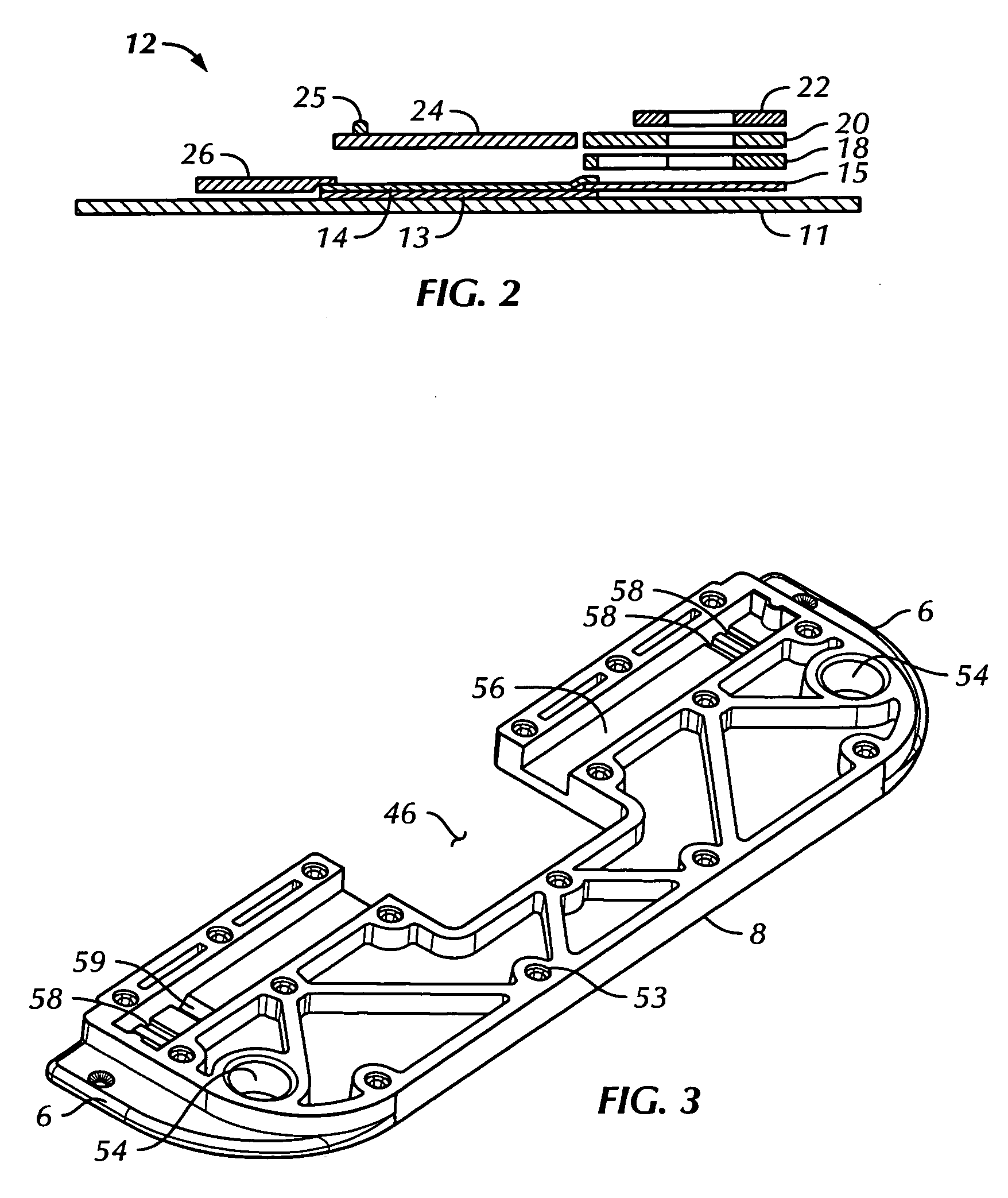
[0039]With reference now to FIGS. 1 to 5, directed flow assay device 10 in accordance with the present invention comprises immunoassay test strip 12, which has porous analytical membrane 14 mounted adjacent to and generally parallel with support member 11. Adhesive layer 13 (FIG. 2) anchors analytical membrane 14 to support member 11. The analytical membrane has a first end and a second end.

[0040]Superparamagnetic particles (not shown) may be present in the sample preparation outside the device. These particles are configured to bind with the ta...


PUM

PropertyMeasurementUnit
Transparencyaaaaaaaaaa
Magnetismaaaaaaaaaa
Superparamagnetismaaaaaaaaaa

Abstract

A diagnostic assay device that directs an applied sample to the analytical membrane of a directed flow device. The device has a sample receiving port defined by layers of built-up material on one end of the test strip. The port contains the sample and specifically directs it to the membrane in a controlled fashion. Additional features include configuration of the housing in a general C-shape with the test strip spanning the opening of the C-shape to allow access by a reader device. A preferred method employs superparamagnetic particles to label the target analytes for detection and measurement by means of an electromagnetic reader device.

Description

BACKGROUND OF THE INVENTION[0001]1. Field of the Invention[0002]The present invention relates generally to immunoassays, receptor-, cellular-, and molecular-based assays, and liquid delivery devices incorporating the same. More specifically it relates to an analytical assay or test device containing a liquid delivery element and may contain reagents for detection of an analyte of interest.[0003]2. Discussion of Related Art[0004]Various chromatographic and microfluidic immunoassay techniques have been available for some time. For example, immune-based latex agglutination tests for detecting a factor associated with rheumatoid arthritis were used as early as 1956 (Singer et al., Am. J. Med. 22:888-892 (1956)). Tests that can be performed with such chromatographic and fluid systems often involve immunoassays, which depend on the specific interaction between an antigen and a corresponding antibody. Immunoassays therefore have gained consideration as an important and convenient means of ...

Claims


Application Information

Patent Timeline
IPC IPC(8): G01N33/551C12M3/00
CPCB01L3/5023B01L9/52B01L2200/026B01L2300/0825G01N33/54326Y10S436/81G01N33/558Y10S435/81Y10S436/807Y10S436/808Y10S435/805G01N33/54386G01N30/26G01N33/53G01N33/54388
Inventor LABORDE, RONALD T.CHOW, HERBERT S.
Owner QUANTUM DESIGN
Why Eureka
Try Eureka