
Diagnosis of equipment failures using an integrated approach of case based reasoning and reliability analysis

a reliability analysis and equipment failure technology, applied in the direction of instruments, testing/monitoring control systems, process and machine control, etc., can solve the problems of critical data, waste of time and resources, and difficulty in identifying equipment failures, so as to reduce the need for further repair, improve the probability of failure of the component, and reduce the diagnosis time

Inactive Publication Date: 2007-12-13
GLOBALFOUNDRIES INC
View PDF11 Cites 46 Cited by
  • Summary
  • Abstract
  • Description
  • Claims
  • Application Information

AI Technical Summary

Benefits of technology

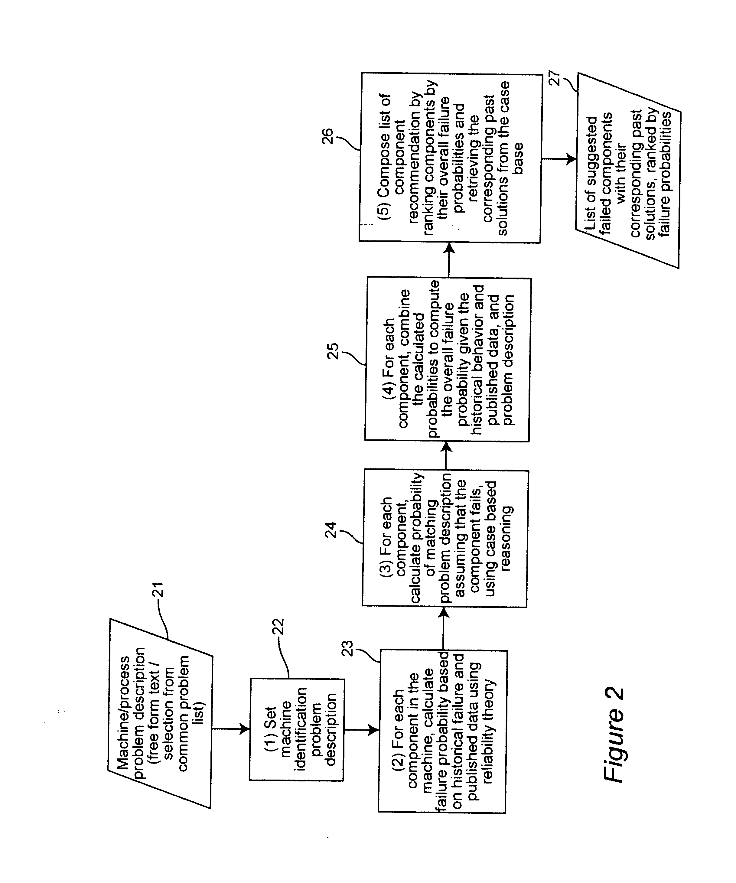
The invention provides a method for a computational engine to help repair technicians quickly and accurately diagnose failures in equipment. The method integrates two approaches: case-based reasoning and reliability analysis. It suggests a list of failed components based on their likelihood of failure, ranked by decreasing probability of failure. This helps the technician quickly focus on a few likely failed components and reduces the time it takes to diagnose the problem. The method also takes advantage of the know-how of a group of people and makes use of the latest data sent to the system. Statistical reliability analysis is used to quantitatively analyze the reliability of the equipment and predict the likelihood of failure. Overall, the method provides a consistent, easily understood approach to diagnosing and repairing equipment failures.

Problems solved by technology

When the equipment is complex with many failure modes (such as computer-controlled production equipment, aircraft, or large scale computing equipment), and / or when the repair technician is less experienced (such as the case in many industries where labor turnover is high), the diagnosis task may take considerable time.
Further, failures may often be diagnosed incorrectly, resulting in wasted time and resources of replacing a working part and another iteration of diagnosis-repair.
On the other hand, in many industries (e.g., semiconductor manufacturing, airlines, critical data centers) unexpected down time of equipment can be very costly.

Method used


Image

  • Diagnosis of equipment failures using an integrated approach of case based reasoning and reliability analysis
  • Diagnosis of equipment failures using an integrated approach of case based reasoning and reliability analysis
  • Diagnosis of equipment failures using an integrated approach of case based reasoning and reliability analysis

Examples


Embodiment Construction

[0025] In the situation when a piece of equipment, such as a machine on the production shop floor, has failed, the immediate goal is to diagnose the failure to determine what needs to be done to bring the equipment back to a running state. To this end we propose a decision support system to help the maintenance technician perform the equipment diagnosis.

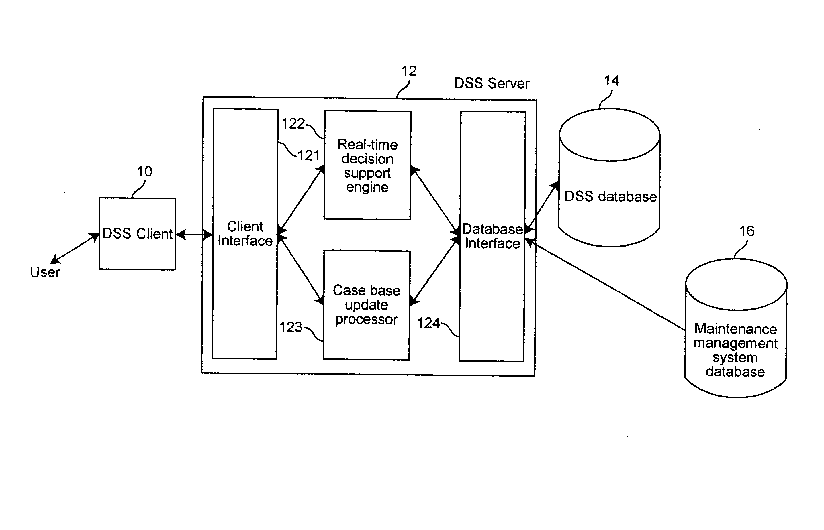
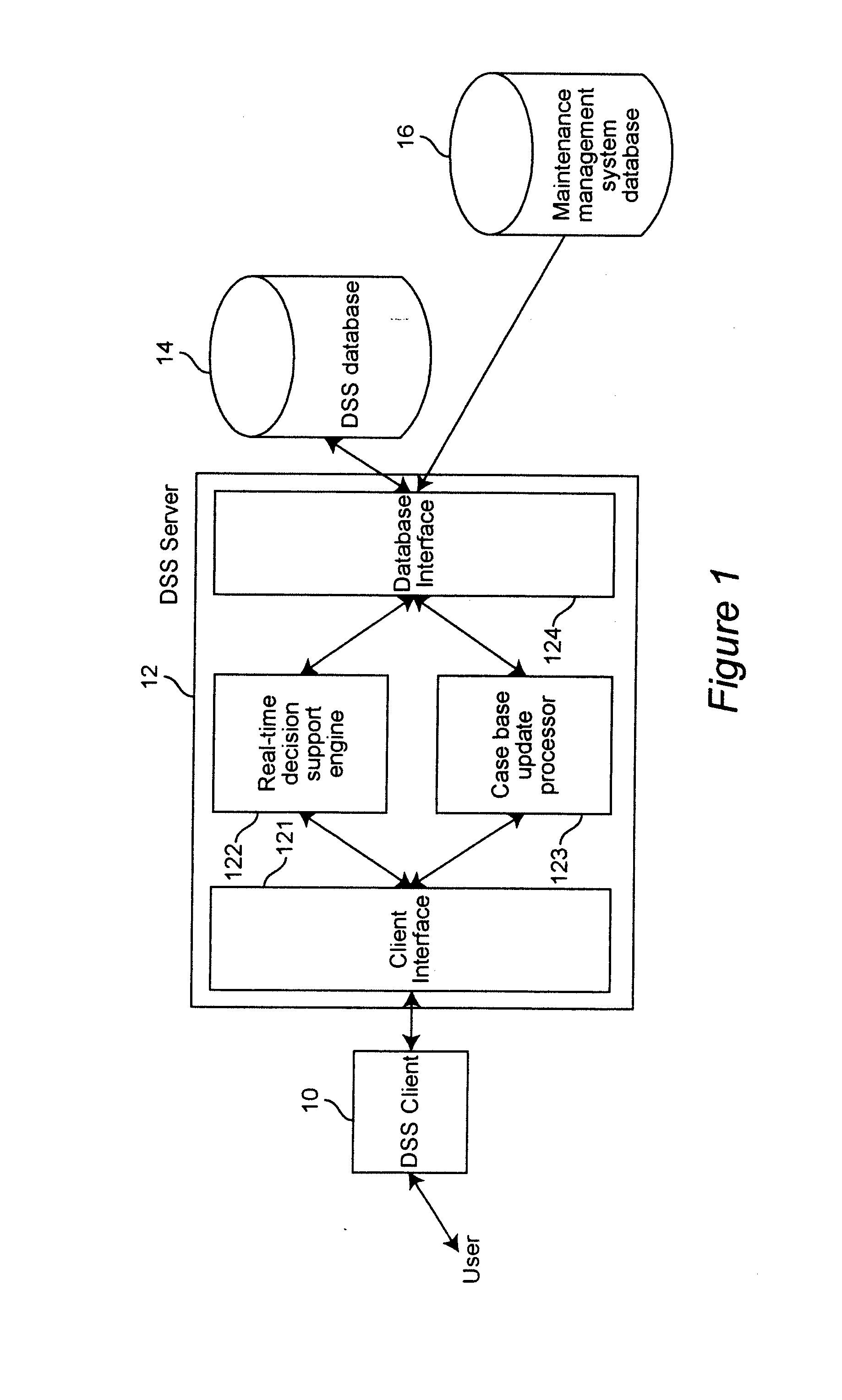
[0026]FIG. 1 shows a typical architecture of such a decision support system (DSS) for equipment diagnosis. Referring to the figure, we describe the decision support system in detail. The DSS client 10 is the user interface to the DSS server 12 through which the maintenance technician interacts with the system. The key inputs to the system, entered by the technician, are the identification of the machine or machine-process combination, a problem description in free form text, or as a selection out of a list of common problem descriptions, or a combination of both. The DSS client 10 will also display the results of the system computat...


PUM


Abstract

Equipment failures are diagnosed using an integrated approach of case-based reasoning (CBR) and statistical reliability analysis. The method outputs a single list of suggested failed components, ranked by an overall probability of failure, and their associated past solutions from the case base. The overall probability of failure is calculated using the combined logic of case based reasoning and statistical reliability analysis. The method is typically used in a real-time decision support system to aid equipment diagnosis by a maintenance technician working in the field.

Description

BACKGROUND OF THE INVENTION [0001] 1. Field of the Invention [0002] The present invention relates to decision support software in diagnosing equipment failures, such as the cases when production equipment fails unexpectedly. This invention provides a method to be used in a computational engine to help the user pinpoint the failed component in a complex machine with a large number of components. [0003] 2. Background Description [0004] Consider the situation when a piece of equipment, such as a machine on the production shop floor, has failed. An immediate task is to diagnose the failure to determine what needs to be done to bring the equipment back to a running state. In particular, the failed component(s), among the possibly large number of candidates, have to be identified and then repaired or replaced. We focus on the first step: diagnosis where the failed component(s) is identified. When the equipment is relatively simple (such as a household appliance) or when the repair technic...

Claims


Application Information

Patent Timeline
Patent Type & Authority Applications(United States)
IPC IPC(8): G06F11/00G06F15/18G05B23/02G06F17/00
CPCG05B23/0275Y10S707/99948Y10S707/99945
Inventor LEUNG, YING TATPARIJA, GYANA RANJANSHARMA, SAMIR
Owner GLOBALFOUNDRIES INC
Learn More