Contactless Energy Supply for Moving Consumers

Inactive Publication Date: 2007-12-20
REXROTH INDRAMAT
View PDF18 Cites 18 Cited by
  • Summary
  • Abstract
  • Description
  • Claims
  • Application Information

AI Technical Summary

Benefits of technology

[0020] The advantages of an industrial machine according to the present invention are particularly efficiently utilized if the machine includes a plurality of secondary parts which execute a motion synchronous with the process according to predetermined process rules. A plurality of seconda

Problems solved by technology

Disadvantages of the system are that, on the one hand, the inductive energy coupling is not without gaps along the route, and, on the other hand, for the generation of an alternating field of high frequency, generally an additional expenditure for material, manufacturing and costs for the implementation is required, which increases in proportion to the route length, and therewith makes the components more expensive in an extreme manner (see, e.g., FIG. 6; column 11, lines 14 ff), as well as requiring regular maintenance.
Consequently, similar disadvantages derive from this U.S. patent document as in the case of the arrangement described in European patent document EP 0580 107.
Because of the induced voltage of an additional energy supply field in the field-generating coils used for generating the propulsion field (traveling field), and the utilization of a linear motor component (primary part) that is pre-existing, and that is connected therewith, this arrangement saves the additio

Method used


Image

  • Contactless Energy Supply for Moving Consumers
  • Contactless Energy Supply for Moving Consumers
  • Contactless Energy Supply for Moving Consumers

Examples


Example

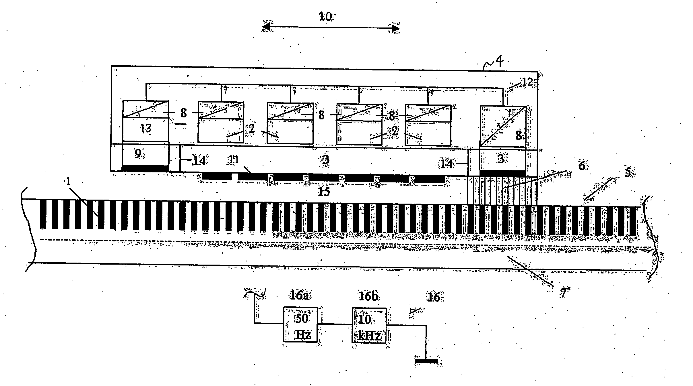
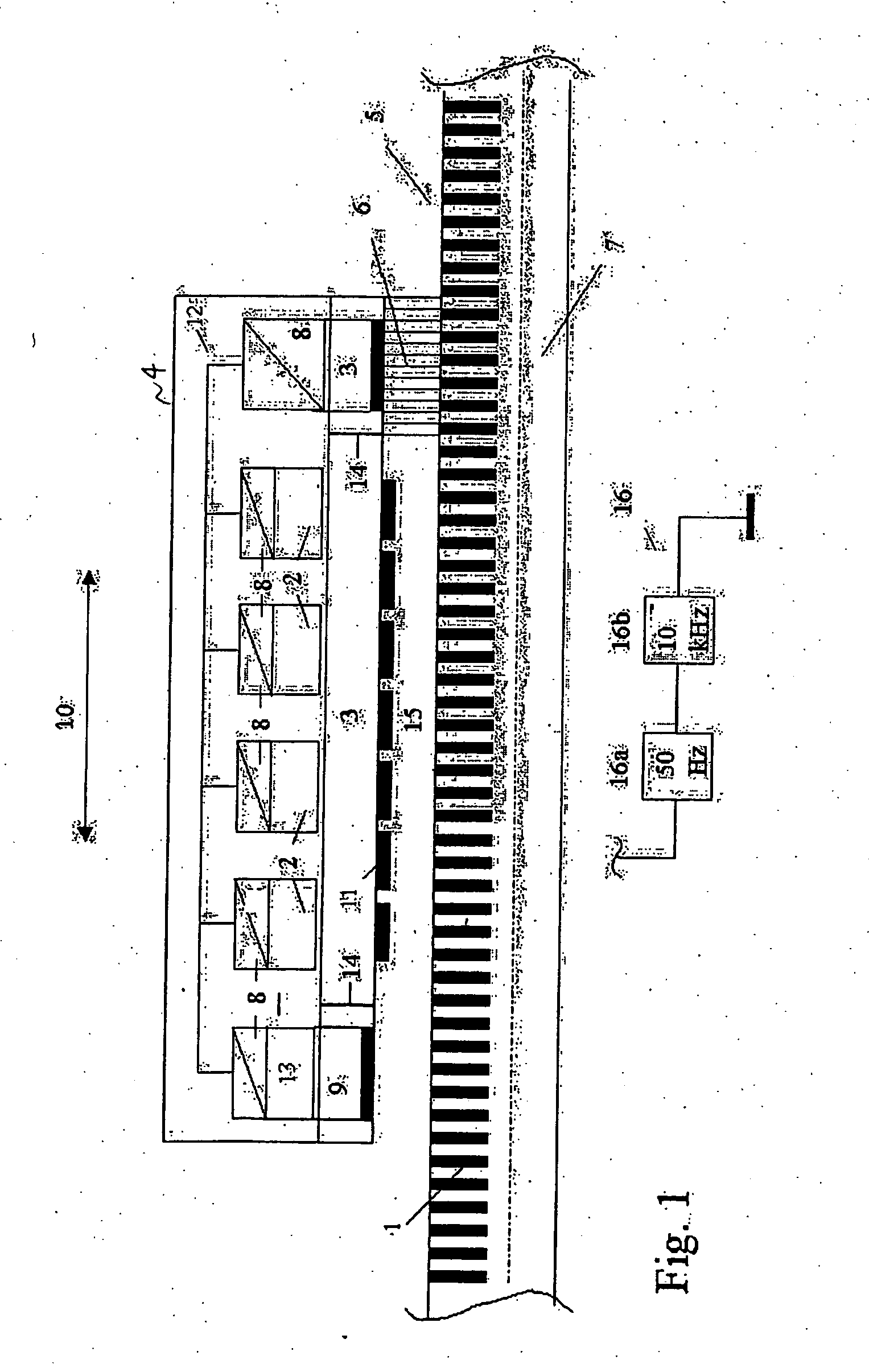
[0026] The linear motor shown in FIG. 1 is made up of a secondary part / secondary parts 4 (only one shown here for clarity sake) and a primary part / primary parts 5, which form a motion path (only one segment shown here for clarity sake). The overall arrangement is shown in a cross-section which is parallel to the possible direction of motion 10 along the center axis.

[0027] Permanent magnets 11 are situated on the lower side of secondary part 4, which is opposite primary part 5. The field of this permanent magnet 11 interacts with the propulsion field or moving field of field-generating coils 1 and secondary part 4, because of the resulting Lorentz force. On the upper side of secondary part 4, consumers 2 are situated which are supplied with energy using voltage and / or level converter 8. In this example, energy supply interface 3 is docked to the secondary part on a side 14 that extends transversely to the direction of motion. Energy interface 3 could in principle be mounted at any o...


PUM


Abstract

A contactless energy supply for electrical consumers mounted on the mobile part of a linear motor is provided, the energy supply being provided without additional voltage sources. A higher frequency energy supply field is superposed over the propulsion field, the energy supply field being inductively decoupled using the energy transmitting interface of the secondary part, and supplying consumers mounted on the secondary part with energy.

Description

FIELD OF THE INVENTION [0001] The present invention relates to supplying electrical loads (or consumers) on the secondary part (moving part) of a linear motor. BACKGROUND INFORMATION [0002] European Patent document EP 0580 107 shows a magnetic suspension system which is designed for transport purposes using straight and curved path sections. The crucial point, in this instance, is the control of the air gap, as a function of the load of the secondary part, using a regulating device fixed to the secondary part. This regulation device is supplied with energy in a contactless manner, via an induction loop having a 10 kHz voltage source. The induction loop is, however, only present at the straight route sections. For travel on curves, a back-up battery situated on the suspension vehicle has to provide energy. Disadvantages of the system are that, on the one hand, the inductive energy coupling is not without gaps along the route, and, on the other hand, for the generation of an alternati...

Claims


Application Information

Patent Timeline
IPC IPC(8): B60L13/03H02J7/35B23Q1/00H02P25/06
CPCH02P25/06B23Q1/0009Y02P90/50
Inventor SCHEMM, EBERHARDSCHNURR, BERND
Owner REXROTH INDRAMAT
Why Eureka
Try Eureka