
High Resolution Analytical Probe Station

a probe station and high-resolution technology, applied in the direction of fault location by increasing the destruction at fault, semiconductor/solid-state device testing/measurement, instruments, etc., can solve the problem that modern structures have now reached a size that no longer allows viewing with standard light microscopes, and the amount of unwanted insulator charging is getting larger. , to achieve the effect of reducing the duty cycle of high-resolution microscopes, reducing the risk of specimen damage, and reducing the amount of unwanted

Inactive Publication Date: 2007-12-20
MICROMANIPULATOR
View PDF50 Cites 29 Cited by
  • Summary
  • Abstract
  • Description
  • Claims
  • Application Information

AI Technical Summary

Benefits of technology

"The present invention is a method and system for probing a specimen using high resolution microscopy, such as a scanning electron microscope or a Focus Ion Beam system, to identify locations of electrically conductive terminals on the specimen. The invention allows for the precise positioning of probes on the surface of the specimen for acquiring and conveying electrical test signals inside a vacuum chamber. The computer can communicate with motorized manipulators and probes for analyzing the specimen. The invention also includes a flexible system for different guarding and shielding schemes, heat insulating materials, and radiation shields to compensate for heat and unwanted movement or drift. The probes can include extended cladding to minimize unwanted insulator charging, and a touchdown sensing mechanism to reduce damage to the specimen. The duty cycle of the high resolution microscope is preferably reduced as by a shuttering system to minimize damage to the DUT."

Problems solved by technology

Although the diameters of wafers are getting larger, the structures constructed on and in those wafers are getting smaller.
However, modern structures have now achieved a size that no longer allows viewing with standard light microscopes.
With the industry integrated circuit design rules driving towards 0.18 micron features and smaller, most advanced optical light microscopes cannot be relied upon to accurately identify the electrically conductive terminals from the conductive path indicia of the surface of the integrated circuit specimens under test.
Additionally, when viewing very small features on a specimen, the optical microscope lens often must be positioned so close to the specimen that it may interfere with the test probes.

Method used


Image

  • High Resolution Analytical Probe Station
  • High Resolution Analytical Probe Station
  • High Resolution Analytical Probe Station

Examples


Embodiment Construction

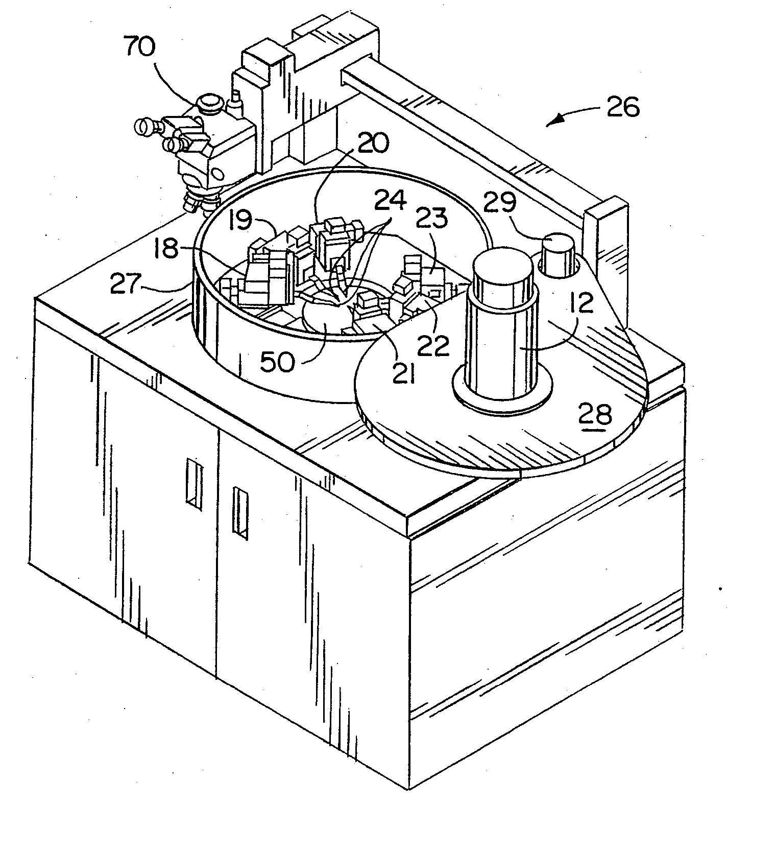
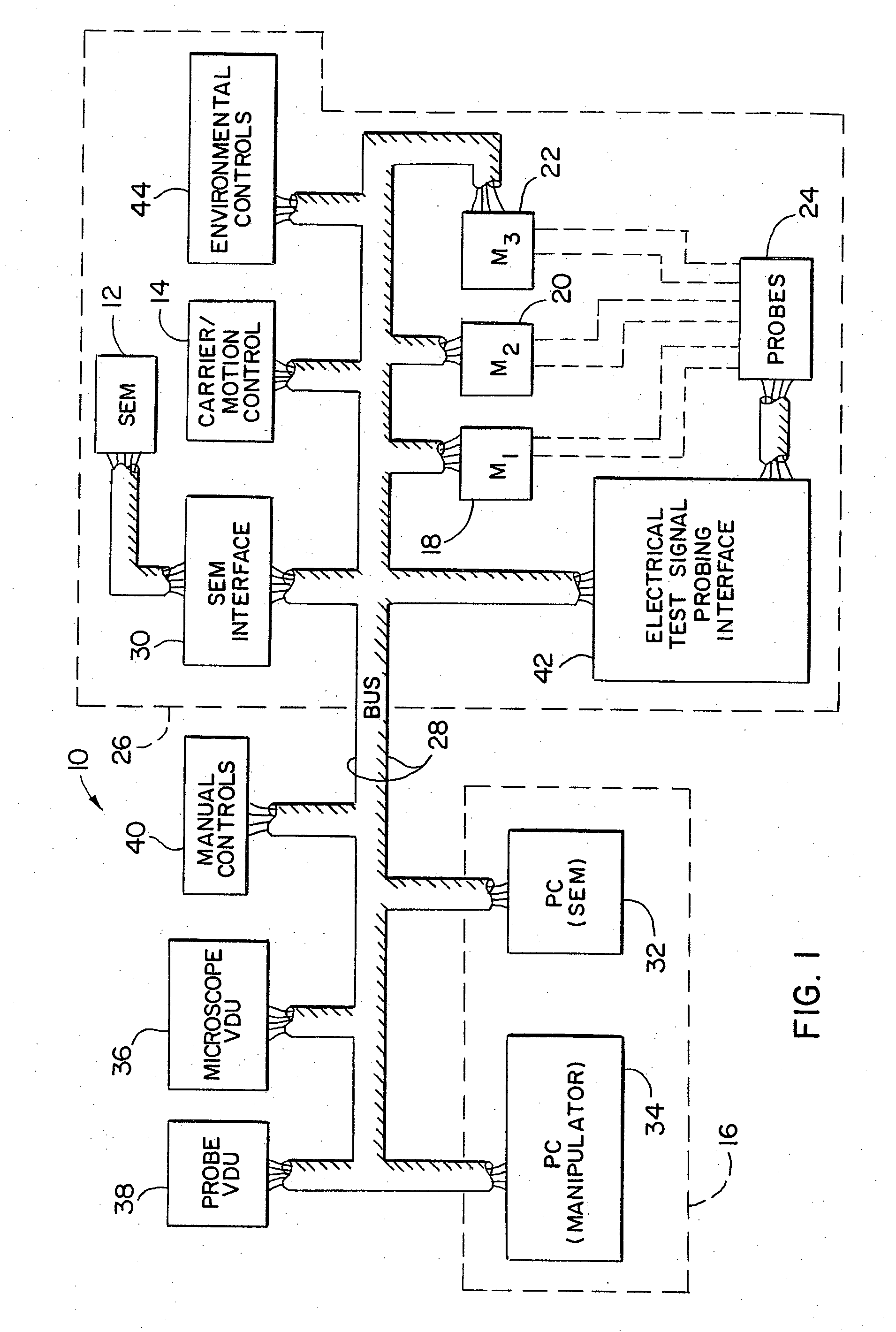
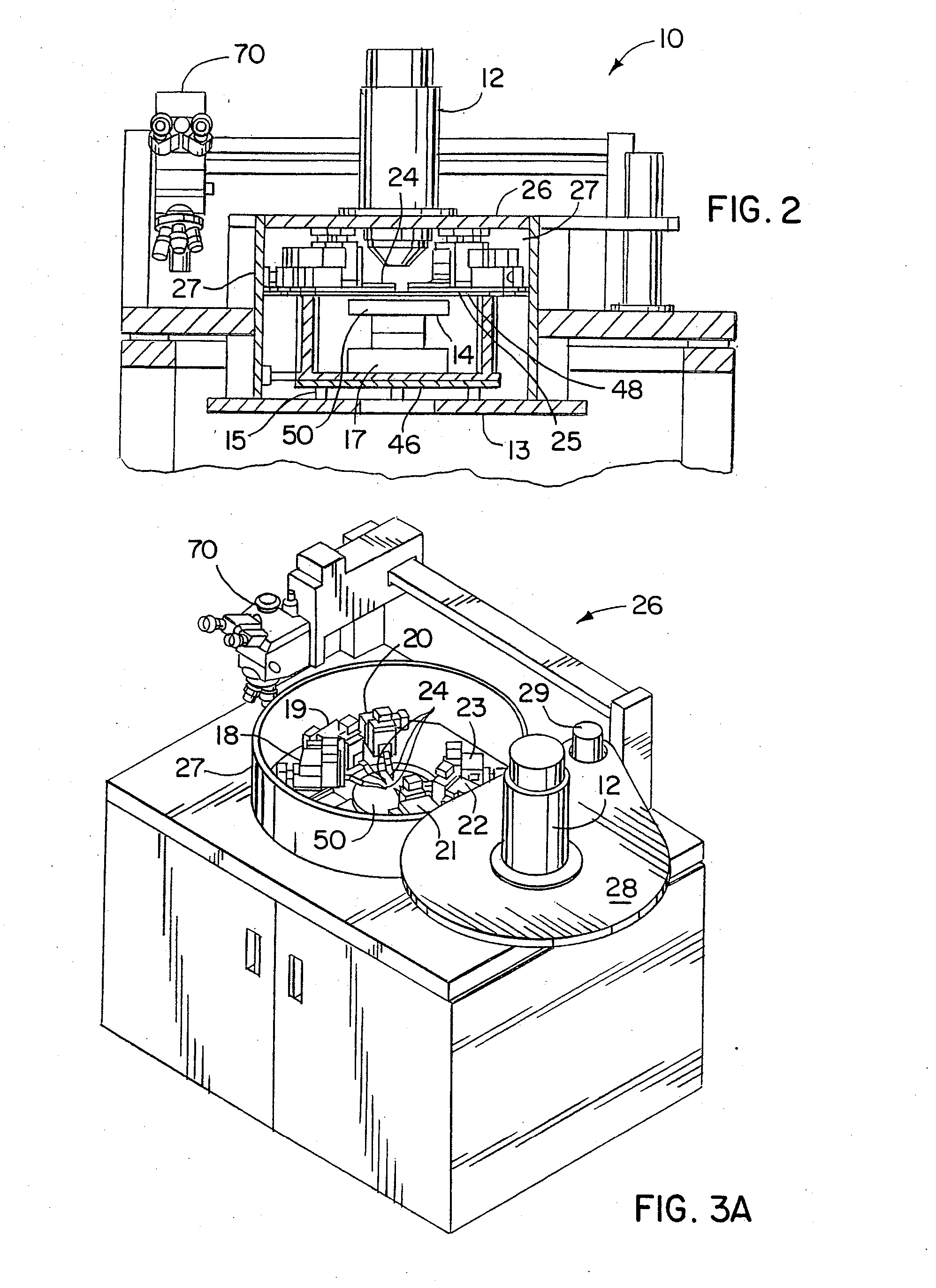
[0049] Referring to the drawings and especially to FIGS. 1 and 2, a system 10 is shown for high resolution analytical probing of an integrated circuit specimen, (e.g., a semiconductor wafer 50). The system 10 is capable of applying electrical test signals to an integrated circuit specimen 50, which may include whole wafers, packaged parts, or wafer fragments. Thus the system 10 may probe entire wafers in addition to a large variety of similarly sized specimens. A conventional scanning electron microscope (SEM), an X-ray microscope for material analysis during probing functions, or a Focus Ion Beam (FIB) system 12, may be employed for enhanced capabilities. Thus, the prober may be integrated into FIB systems as well as SEM systems. The embodiment described herein uses a SEM provided by R.J. Lee Instruments Ltd. which is positioned for observing a surface of the specimen 50 exposing electrically conductive terminals on the specimen 50. See, e.g., FIG. 4, discussed below. The system 10...


PUM


Abstract

A method and system for probing with electrical test signals on an integrated circuit specimen using a high resolution microscope positioned for observing a surface of the specimen exposing electrically conductive terminals thereon. A housing is provided with a carrier therein for supporting the specimen in relation to the microscope and a probe assembly is positionable on the surface of the specimen for conveying and acquiring electrical test signals to and from the specimen. A drive system is provided for shifting at least one of the probe and the carrier to a predetermined test position. In one form the system has a heat shield for protecting one of the probe assembly and the carrier from heat energy generated upon operation of the drive system, and in another form, the system has an environmental control for maintaining a desired temperature within the housing so that accurate measurements may be taken from the specimen.

Description

CROSS-REFERENCE TO RELATED APPLICATION [0001] This application is a divisional of prior application Ser. No. 10 / 816,114, filed Apr. 1, 2004, now U.S. Pat. No. 7,180,317, which is a divisional of prior application Ser. No. 10 / 119,346, filed Apr. 8, 2002, now U.S. Pat. No. 6,744,268, which is a continuation-in-part of prior application Ser. No. 09 / 774,249, filed Jan. 30, 2001, now U.S. Pat. No. 6,621,282, which is a continuation of prior application Ser. No. 09 / 527,874, filed Mar. 17, 2000, now U.S. Pat. No. 6,191,598, which is a continuation of prior application Ser. No. 09 / 140,910, filed Aug. 28, 1998, now U.S. Pat. No. 6,198,299, which are hereby incorporated herein by reference in their entirety.BACKGROUND OF THE INVENTION [0002] The invention relates in general to the use of high resolution microscopy probe stations, and particularly to methods and system for probing with electrical test signals on integrated circuit (IC) specimens using a scanning electron microscope (SEM) posit...

Claims


Application Information

Patent Timeline
Patent Type & Authority Applications(United States)
IPC IPC(8): G01R31/02G01R31/28G01R1/06G01R31/307H01J37/20H01L21/66
CPCG01R1/07392G01R31/2851G01R31/307G01R31/2891G01R31/2887G01R1/025H01L22/00
Inventor HOLLMAN, KENNETH F.
Owner MICROMANIPULATOR
Learn More