
Curable Composition and Elastic Roller Therefrom

Inactive Publication Date: 2007-12-20
KANEKA CORP
View PDF4 Cites 0 Cited by
  • Summary
  • Abstract
  • Description
  • Claims
  • Application Information

AI Technical Summary

Benefits of technology

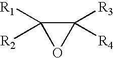
[0005] The present inventors made intensive investigations in an attempt to solve the problems mentioned above and found that when use is made of a curable composition comprising (A) an organic polymer containing, within the molecule, at least one alkenyl group capable of undergoing hydrosilylation but not containing at least one group selected from an alkoxy group and an epoxy group, (B) a compound containing at least two hydrosilyl groups within the molecule, (C) a hydrosilylation catalyst and (D) a compound containing at least one structure selected from the structure represented by the general formula (1); M-OR   (1) (wherein M is an atom selected from a silicon atom, an aluminum atom and a titanium atom, and R is a hydrocarbon group); and an epoxy group structure, the adhesion between the elastic layer made from the curable composition and the covering layer surrounding the elastic layer can be improved and the interfacial peeling between the elastic layer and covering layer can be thereby prevented. Such and other findings have led to completion of the present invention.

Problems solved by technology

This is because when the roller rotates while contacting with another member, contacting-due friction occurs on the roller surface and, in the layer interface weak in adhesion, the covering layer may peel off.
An increase in the speed of operation of an OA appliance, namely an increase in the number of prints per minute, means that the number of roller revolutions per minute also increases; the roller surface suffers stronger stress than before, so that peeling may occur from those layer interface sites where the adhesion is insufficient, possibly causing deteriorations in image quality.

Method used


Image

  • Curable Composition and Elastic Roller Therefrom

Examples


example 1

[0048] A mixture was prepared by kneading 500 g of allyl-terminated polyoxypropylene (product name: ACX004-N, manufactured by Kaneka Corporation; corresponding to component A) with 70 g of Carbon Black #3030B (manufactured by Mitsubishi Chemical Corporation; corresponding to component F) using a 3-roll mill. Then, 16 g of polyorganohydrogensiloxane (product name: CR100, manufactured by Kaneka Corporation; corresponding to component B), 350 μL of a bis(1,3-divinyl-1,1,3,3-tetramethyldisiloxane)-platinum complex catalyst (platinum content 3% by weight, xylene solution; corresponding to component C), 170 μL of dimethyl maleate-and 5 g of tetraethoxysilane (corresponding to component D) were uniformly admixed with the mixture mentioned above. The resulting curable composition was debubbled using a vacuum debubbling agitator (manufactured by Sea-tec Co., Ltd.) for 90 minutes. This curable composition was injected into a mold (inside diameter 16 mm) with a SUS stainless steel shaft having...

example 2

[0049] A mixture was prepared by kneading 500 g of allyl-terminated polyoxypropylene (product name: ACX004-N, manufactured by Kaneka Corporation; corresponding to component A) with 70 g of #3030B (manufactured by Mitsubishi Chemical Corporation; corresponding to component F) using a 3-roll mill. Then, 16 g of polyorganohydrogensiloxane (product name: CR100, manufactured by Kaneka Corporation; corresponding to component B), 350 μL of a bis(1,3-divinyl-1,1,3,3-tetramethyldisiloxane)-platinum complex catalyst (platinum content 3% by weight, xylene solution; corresponding to component C), 170 μL of dimethyl maleate and 5 g of acetoalkoxyaluminum diisopropylate (product name: AL-M, manufactured by Ajinomoto Fine-Techno. Co. Inc; corresponding to component D) were uniformly admixed with the mixture mentioned above. An elastic layer roller was manufactured in the same manner as in Example 1 and tested for ASKER-C hardness and, after roller covering layer formation in the same manner as in ...

example 3

[0050] A mixture was prepared by kneading 500 g of allyl-terminated polyoxypropylene (product name: ACX004-N, manufactured by Kaneka Corporation; corresponding to component A) with 70 g of #3030B (manufactured by Mitsubishi Chemical Corporation; corresponding to component F) using a 3-roll mill. Then, 16 g of polyorganohydrogensiloxane (product name: CR100, manufactured by Kaneka Corporation; corresponding to component B), 350 μL of a bis(1,3-divinyl-1,1,3,3-tetramethyldisiloxane)-platinum complex catalyst (platinum content 3% by weight, xylene solution; corresponding to component C), 170 μL of dimethyl maleate and 5 g of tetrabutoxytitanium (corresponding to component D) were uniformly admixed with the mixture mentioned above. An elastic layer roller was manufactured in the same manner as in Example 1 and tested for ASKER-C hardness and, after roller covering layer formation in the same manner as in Example 1, the roller was tested for interfacial peeling between the elastic layer ...


PUM

PropertyMeasurementUnit
Angleaaaaaaaaaa
Electrical conductivityaaaaaaaaaa
Compositionaaaaaaaaaa

Abstract

There has been a problem, in rollers to be incorporated in image forming apparatus utilizing the technology of electrophotography, that an elastic roller which comprises at least one elastic layer formed around an electrically conductive shaft and at least one covering layer formed on the outer surface of the elastic layer undergoes interfacial peeling possibly occurring when the roller rotates while contacting with other members. Using a curable composition comprising, as essential components, (A) an organic polymer containing, within the molecule, at least one alkenyl group capable of undergoing hydrosilylation but not containing an alkoxy group and / or an epoxy group, (B) a compound containing at least two hydrosilyl groups within the molecule, (C) a hydrosilylation catalyst and (D) a compound containing the structure represented by the general formula (1); M-OR   (1) (wherein M is an atom selected from a silicon atom, an aluminum atom and a titanium atom, and R is alkyl, alkenyl or the like groups); and / or an epoxy group structure, has led to a solution of the above subject.

Description

TECHNICAL FIELD [0001] This invention relates to a curable composition which, upon being cured, can give an elastomer capable of adhering to the surface of another material, or to the field of technology of curable compositions for the manufacture of elastic rollers to be incorporated in image forming apparatus such as electrophotograpic copiers, laser beam printers, facsimiles, composite office automation appliances comprising these or the like, in which the technology of electrophotography is utilized. BACKGROUND ART [0002] In the above-mentioned technical field, such rollers are used as charging rollers, developing rollers, fixing rollers and the like, and they are required to have different characteristics according to the respective uses. These rollers are each provided with a plurality of resin layers around a conductive shaft according to the characteristics required. For example, a low-hardness elastic layer is provided for the purpose of securing a nip width on the occasion...

Claims


Application Information

Patent Timeline
IPC IPC(8): C08L83/05C08L101/02F16C13/00G03G15/00G03G15/20
CPCG03G15/2057C08L83/04
Inventor KAMITE, JUNKUCHIYAMA, TAKASHI
Owner KANEKA CORP
Features
  • Generate Ideas
  • Intellectual Property
  • Life Sciences
  • Materials
  • Tech Scout
  • Unparalleled Data Quality
  • Higher Quality Content
  • 60% Fewer Hallucinations
Learn More