Method of reducing a wave front aberration, and computer program product

Active Publication Date: 2007-12-27
ASML NETHERLANDS BV
View PDF6 Cites 33 Cited by
  • Summary
  • Abstract
  • Description
  • Claims
  • Application Information

AI Technical Summary

Benefits of technology

[0010]It is an object of the present invention to reduce an effect of an optical wave aberration of a projection system of a lithograp

Problems solved by technology

The beam of radiation propagating through the projection lens causes a local, generally non-uniform heating of optical elements.
Such a heating may cause thermal deformations of the projection lens elements and hence, an optical wave aberration error.
However, compensation results obtained with the conventional techniques in the presence of higher-order wave-abe

Method used


Image

  • Method of reducing a wave front aberration, and computer program product
  • Method of reducing a wave front aberration, and computer program product
  • Method of reducing a wave front aberration, and computer program product

Examples


first embodiment

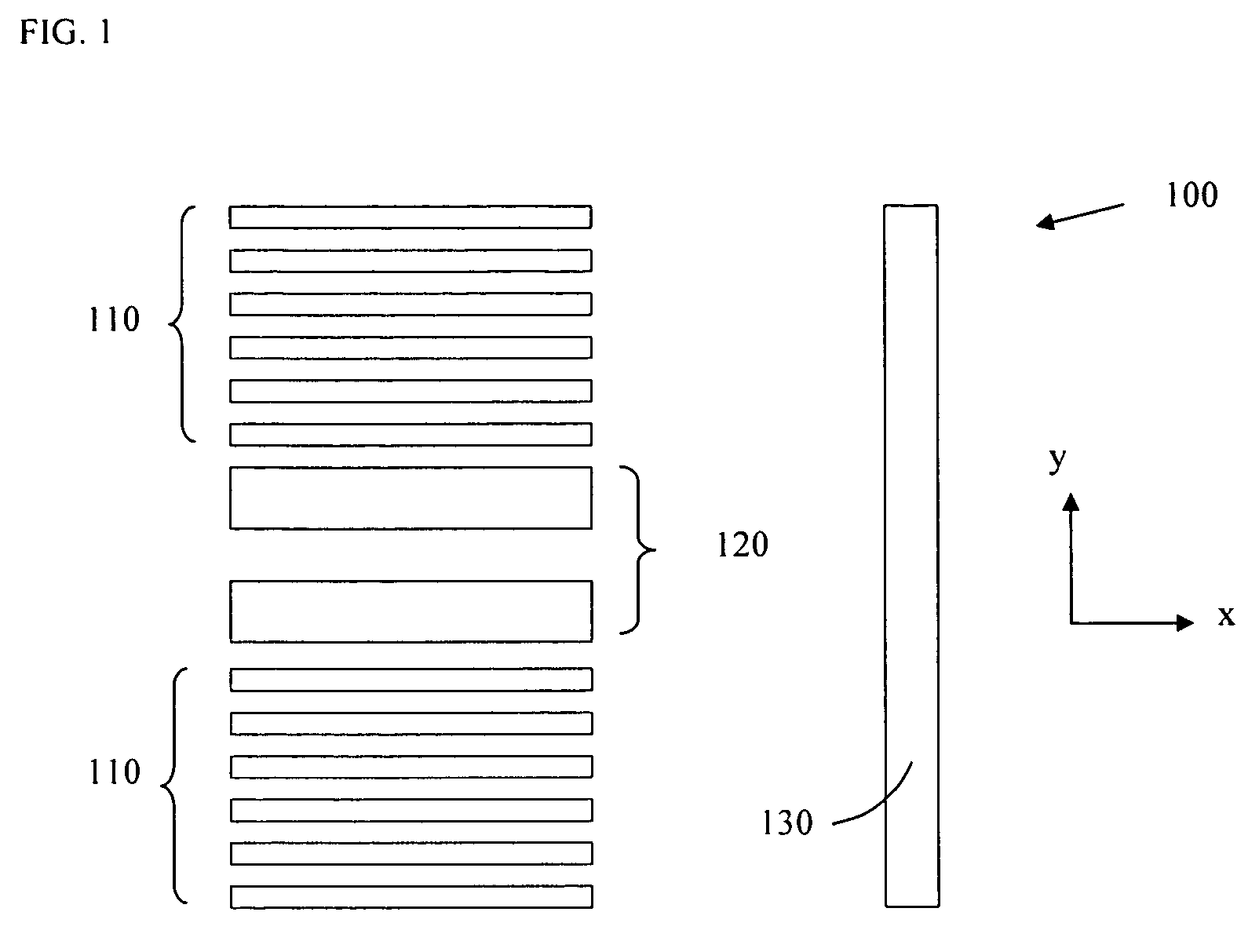
[0025]According to the invention the method of reducing a wave front aberration is used for alleviating effects of local lens heating within a projection system, when in use for executing a lithographic exposure process. A pattern of features of an IC layer includes a product structure 100, illustrated in FIG. 1, having dense lines and spaces 110, of critical dimension CD. The pattern 100 is embodied as a Chrome on Glass pattern, and the lines 110 and 120 are, on the mask, aligned along an x-direction of the lithographic apparatus. The product structure 100 further includes two lines 120 aligned along the x-direction as well and having a width greater than CD, and a similar non-critically sized, isolated line 130 along the y-direction.

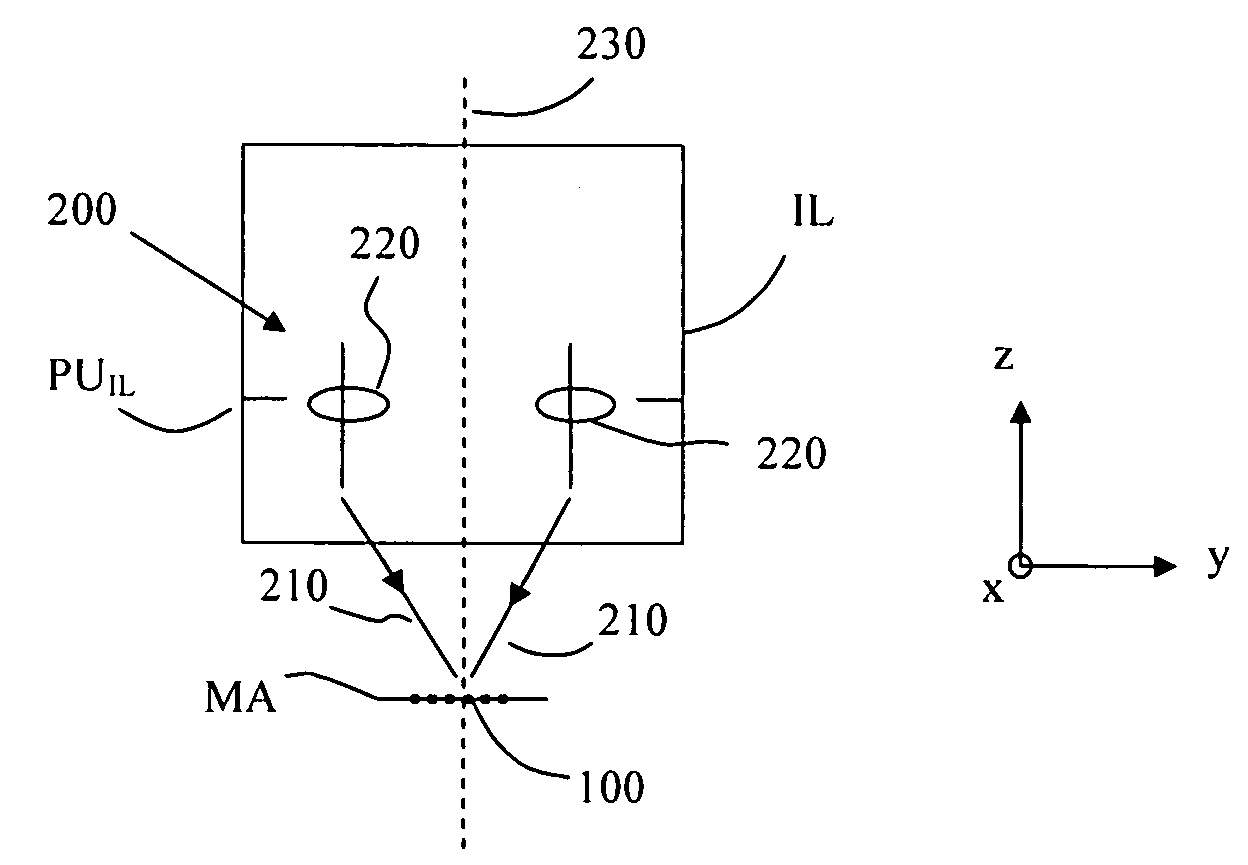
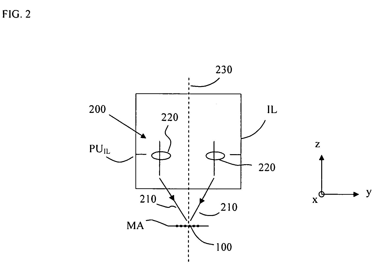
[0026]As illustrated in FIG. 2, a y-dipole illumination mode 200 is used for illuminating the pattern 100 on the mask MA. Two beams of radiation 210 are emanating from two respective areas 220 disposed in a pupil PUIL of an illumination system IL arran...

second embodiment

[0071]According to the invention there is provided a computer program product comprising program code to control the lithographic apparatus to perform a device manufacturing method comprising obtaining information on the wave front aberration ΔW, calculating at least one adjustment ΔSj,k of at least one optical element of the projection system PS for reducing the wave front aberration ΔW, applying the calculated at least one adjustment to the projection system, whereby the calculating includes obtaining information on a spatial distribution I(xp, yp) of radiant intensity in a pupil PUPS of the projection lens PS as present during exposing a radiation sensitive layer on top of a substrate W, selecting a threshold intensity IT in a range between a maximum intensity Imax of the distribution of intensity I(xp, yp) and zero, defining areas in the pupil within which a local intensity is higher than the threshold intensity IT, and limiting the reducing to areas of the wave front correspond...


PUM


Abstract

A method of reducing a wave front aberration is provided for a lithographic process whereby the reducing is based on the selected pattern to be printed and the selected illumination mode used for exposure. Wave front aberrations of a projection system of a lithographic apparatus are measured and reduced by calculating adjustments of optical elements of the projection system and applying the calculated adjustments to the projection system. The calculation of adjustments is based on information on a spatial distribution of radiant intensity in a pupil of the projection system as present during exposing the radiation sensitive layer, and is limited to aberrations in projection lens pupil areas of relative high radiant flux.

Description

BACKGROUND OF THE INVENTION[0001]1. Field of the Invention[0002]This invention relates to a method of reducing a wave front aberration of an optical wave traversing a projection system of a lithographic apparatus and a computer program product comprising program code to control a lithographic apparatus to perform a device manufacturing method.[0003]2. Description of Related Art[0004]A lithographic apparatus is a machine that applies a desired pattern onto a substrate, usually onto a target portion of the substrate. A lithographic apparatus can be used, for example, in the manufacture of integrated circuits (ICs). In that instance, a patterning device, which is alternatively referred to as a mask or a reticle, may be used to generate a circuit pattern to be formed on an individual layer of the IC. This pattern can be transferred onto a target portion (e.g., comprising part of one or several dies) on a substrate (e.g. a silicon wafer). The lithographic apparatus comprises an illuminat...

Claims


Application Information

Patent Timeline
IPC IPC(8): G03B27/42
CPCG03B27/53G03B27/72G03F7/70891G03F7/70258G03F7/706G03F7/70125
Inventor TEL, WIM TJIBBOSTOFFELS, FREERK ADRIAANJORRITSMA, LAURENTIUS CATRINUSUITTERDIJK, TAMMODE KLERK, JOHANNES WILHELMUS
Owner ASML NETHERLANDS BV
Why Eureka
Try Eureka