Devices and methods for absorbing, transferring, and delivering heart energy

Inactive Publication Date: 2007-12-27
VASKA MATTHIAS
View PDF5 Cites 8 Cited by
  • Summary
  • Abstract
  • Description
  • Claims
  • Application Information

AI Technical Summary

Benefits of technology

[0005]The present invention involves absorbing cardiac energy used to pump blood and delivering this energy to another portion of the vascular system in a way that assists the overall function of the heart. For example, the present invention can be used to treat heart failure patients with left ventricular dysfunction who have a relatively healthy right ventricle. The invention may provide active assist to the left ventricle by taking advantage of the unused extra capacity of the healthier right ventricle. The device and method thereby avoid the need for external power while still actively assisting the left ventricle. Of course, the invention may also be used with an active assist which adds pumping energy to the system as well. The invention also benefits from a simple and compact design which facilitates implantation and reliability. Furthermore, some embodiments may be designed to avoid blood contact entirely and be placed on a beating heart using minimally invasive access, thereby minimizing potential complications.
[0006]An energy absorbing portion of the system may be implanted in or on the right side of the heart that is designed to convert right ventricular energy into a form that can be transferred by an energy delivery portion to the left ventricle. For example a device could be configured to change the pressure of a fluid when the right ventricle contracts. This fluid could then be delivered through a lumen to the left ventricle where the change in pressure and / or volume is used to help the left ventricle pump. Because the left and right ventricles contract at the same time, there is no need to provide any synchronization function (i.e., the fluid is moved at the appropriate time). Of course, other devices and methods for absorbing energy from the right ventricle and transferring it to the left ventricle (or vice versa), such as those that incorporate cables and linkages, could be used without departing from the scope of the invention. The energy absorbing element could be formed as a clip configured to fit around the pulmonary artery (PA). This clip may have at least one expandable or compressible member positioned between the clip and the PA. The expandable member may be a bladder containing a fluid. When the heart is in diastole (i.e., ventricles are filling) the blood pressure in the PA is relatively low, and the bladder is configured to gently squeeze the PA in order to reduce its cross-sectional area and volume. This could be accomplished by constructing the bladder with a bias toward a pre-determined expanded shape that provides this squeezing effect when it is under a relatively small amount of stress.
[0007]When the right ventricle contracts the pressure in the PA rises, thereby squeezing the bladder between the PA and the clip which is substantially rigid. The bladder is configured to collapse under these conditions, increasing the pressure of the fluid inside the bladder and forcing the fluid out of a lumen connected to the bladder. The lumen conveys the fluid in a tube and the other end of this lumen is connected to an expandable element that is configured to be placed on the exterior surface of the left ventricular free wall. As the fluid enters the expandable element, pressure is applied to the left ventricular free wall thereby aiding left ventricular contraction. When ventricular contraction (i.e., systole) is complete the pressure in the PA falls, causing the bladder to expand. This pulls fluid out of the expandable element, allowing the left ventricle to fill properly.

Problems solved by technology

This deterioration ultimately reduces the ability of the heart to pump blood, causes a number of severe symptoms, and results in a high mortality rate.
Over time, this additional stress on the right ventricle can cause right ventricular dysfunction.
Reliably providing the amount of energy needed to assist the heart significantly increases the complexity of these assist devices.
These various components increase cost and can result in reliability and ease-of-use problems.
In addition, the implantation of these components can be time consuming and difficult.
Furthermore, the blood-contacting nature of many assist devices results in significant complications (e.g., stroke).
The concept has met with little success.

Method used


Image

  • Devices and methods for absorbing, transferring, and delivering heart energy
  • Devices and methods for absorbing, transferring, and delivering heart energy
  • Devices and methods for absorbing, transferring, and delivering heart energy

Examples


Embodiment Construction

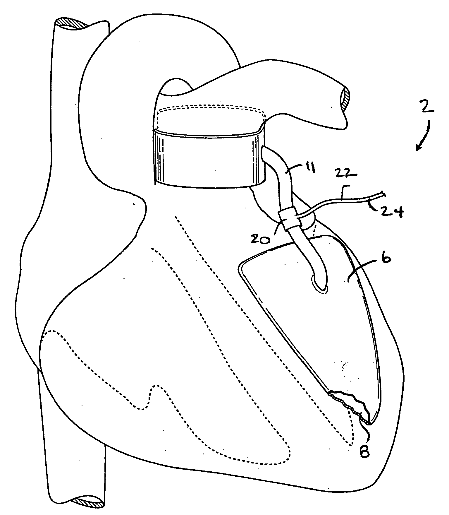
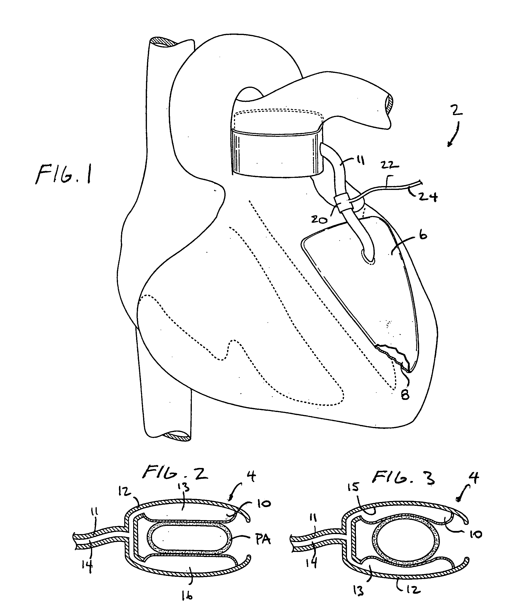
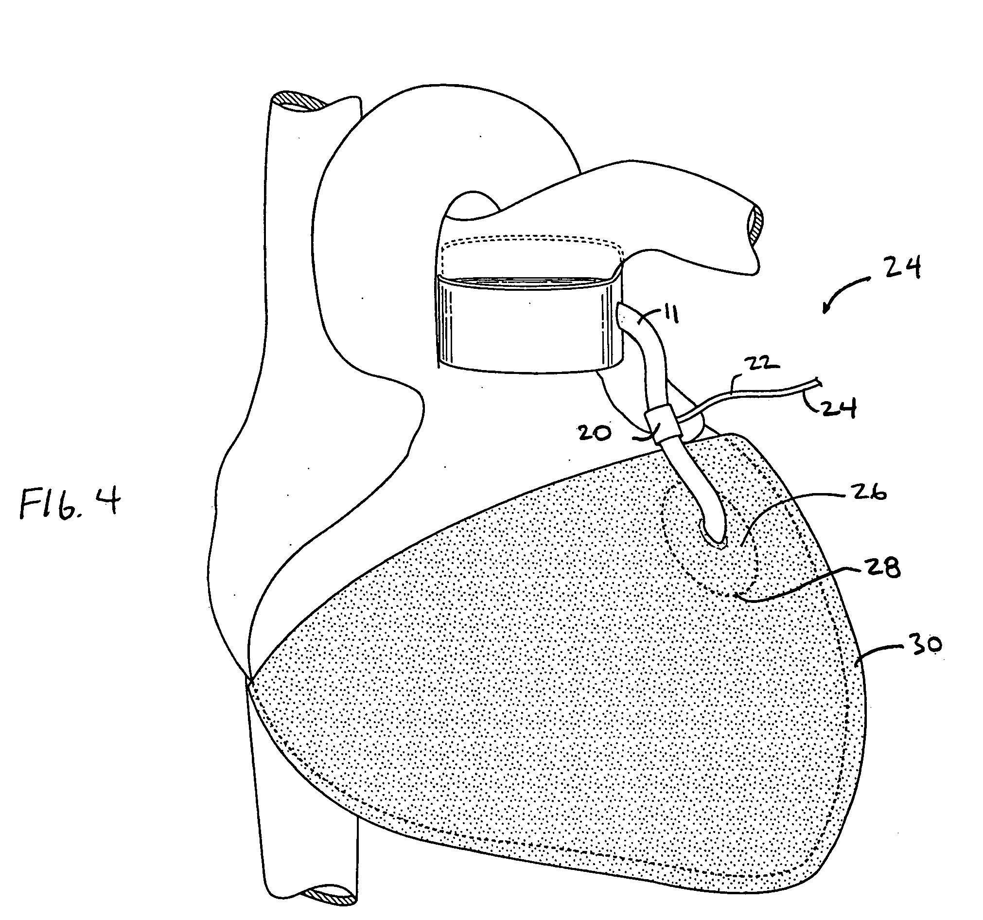
[0024]Referring to FIGS. 1-3, a device 2 for assisting the heart in pumping blood is shown. The device 2 has an energy absorbing element 4 which absorbs pumping energy of the heart. The device 2 also has an energy delivery element 6 which receives energy from the energy absorbing element 4 and uses the energy to provide pumping assistance to the heart. The energy delivery element 6 may include an expandable element 8 placed adjacent to an exterior surface of the left ventricle. The expandable element 8 applies pressure to the exterior surface of the left ventricle during contraction of the left ventricle to assist the left ventricle in pumping blood.

[0025]The energy absorbing element 4 is configured and positioned to absorb pumping energy from the heart when the right ventricle is contracting. The energy absorbing element 4 may be positioned around at least a portion of a blood vessel that is part of the pulmonary arterial tree such as one of the pulmonary arteries. The energy absor...


PUM


Abstract

A device for altering cardiac performance includes an energy absorbing element which absorbs cardiac pumping energy from at least a portion of the heart. The energy may be delivered to another part of the body, such as another portion of the heart, to perform useful work such as providing blood pumping assistance.

Description

BACKGROUND[0001]Heart failure is a serious disease that is caused by deterioration of ventricular muscle. This deterioration ultimately reduces the ability of the heart to pump blood, causes a number of severe symptoms, and results in a high mortality rate.[0002]Many heart failure patients have left ventricular dysfunction wherein the left ventricle is diseased while the right ventricle remains relatively healthy. Because the right and left ventricle are fluidly connected in series, both ventricles must pump the same amount of blood. Therefore with left ventricular dysfunction, the healthier right ventricle is forced to reduce its output to that of the left ventricle. The mechanism by which this occurs is a significant increase in blood pressures against which the right heart must work. Over time, this additional stress on the right ventricle can cause right ventricular dysfunction.[0003]Various electric and pneumatic pumps have been proposed that assist failing hearts in pumping bl...

Claims


Application Information

Patent Timeline
IPC IPC(8): A61M1/12
CPCA61M1/1003A61M1/1037A61M60/882A61M60/289A61M60/187A61M60/191A61M60/468A61M60/161A61M60/17A61M60/139A61M60/295
Inventor VASKA, MATTHIAS
Owner VASKA MATTHIAS
Why Eureka
Try Eureka