Method for augmenting, reducing, and repairing bone with thermoplastic materials

a technology of thermoplastic materials and bone, applied in the field of methods and materials for augmenting and repairing bone, can solve the problems of inconvenient methods, difficult surgery for surgeons to treat osteoporotic fractures in these areas, and failure of angular stable constructs in osteoporotic bone, etc., and achieve the effect of increasing the discontinuity degree of the first thermoplastic structur

Inactive Publication Date: 2008-01-03
DEPUY SYNTHES PROD INC
View PDF1 Cites 66 Cited by
  • Summary
  • Abstract
  • Description
  • Claims
  • Application Information

AI Technical Summary

Problems solved by technology

However, even angular stable constructs fail in osteoporotic bone because of a lack of stability in the bone to screw interface.
Treating osteoporotic fractures in these areas can be very challenging for the surgeon because the screws can not find sufficient purchase in the weak trabecular structure.
Each of these methods has disadvantages.
For example, disadvantages of using PMMA include the permanent non-resorbing nature of PMMA.
It remains within the body after the fracture has healed and removal of the material is nearly impossible once implanted.
PMMA is initially too runny to handle and can quickly become too difficult to implant and the state of the material is not reversible.
PMMA has a minimal ductility, can bind to metals making screw removal difficult, and can be difficult to control the direction of implantation.
PMMA can either extravasate into the canal of the diaphysis (rendering it ineffective), into the joint space or become vascularized (leading to an embolism).
Furthermore, PMMA includes a risk of thermal necrosis due to the exothermic reaction during curing.
The calcium phosphate materials will not properly set unless the surrounding tissue is near 37° C. It can be difficult to control the direction of implantation of calcium phosphates and calcium phosphates can either extravasate into the canal of the diaphysis (rendering it ineffective), into the joint space or become vascularized (leading to an embolism).
Calcium phosphates include suboptimal mechanical properties while they often have adequate compressive strength, they have little tensile strength, flexural strength or ductility.
Furthermore, additional calcium phosphate material will not bond to calcium phosphate material that has already set and the drillability and screwability of the calcium phosphate is limited.
The addition of reinforcing fibers actually renders the cement less advantageous for hardware augmentation since the fiber will be filtered by the trabecular structure surrounding the hardware and will impede perfusion.
However the material remains suboptimal for the application.
PMMA is commonly used for vertebroplasty procedures but suffers from many of the problems stated above.
Calcium phosphate cements can be used as well, but also with the above limitations.
Further, in these types of applications there often exists a need to reduce the fractures or to compress the surrounding bone, which the existing materials are not capable of doing.

Method used


Image

  • Method for augmenting, reducing, and repairing bone with thermoplastic materials
  • Method for augmenting, reducing, and repairing bone with thermoplastic materials
  • Method for augmenting, reducing, and repairing bone with thermoplastic materials

Examples


example 1

PCL Composite Composition

[0089] A PCL / β-TCP composite was produced with the following composition:

[0090] PCL component: Sigma PCL 440744, I.V. 1.59, 20% by weight

[0091]β-TCP component: chronOS granules, 1.4-2.8 mm

[0092] The above components were heated to above 60° C. and kneaded by hand and allowed to cool. A structurally sound, cohesive mass was formed. The composite was reheated and manipulated to simulate manipulation by the surgeon and formed into a ball. It was again allowed to cool.

[0093] The composite material was placed in a solution with Alizarin red S (a red dye selective for calcium). Areas that still had exposed calcium were dyed red and areas encapsulated by polymer were yellow. A significant amount of calcium was free from encapsulation. The same composite was sectioned and the dye had penetrated significant portions of the internal structure demonstrating an interconnected porosity.

example 2

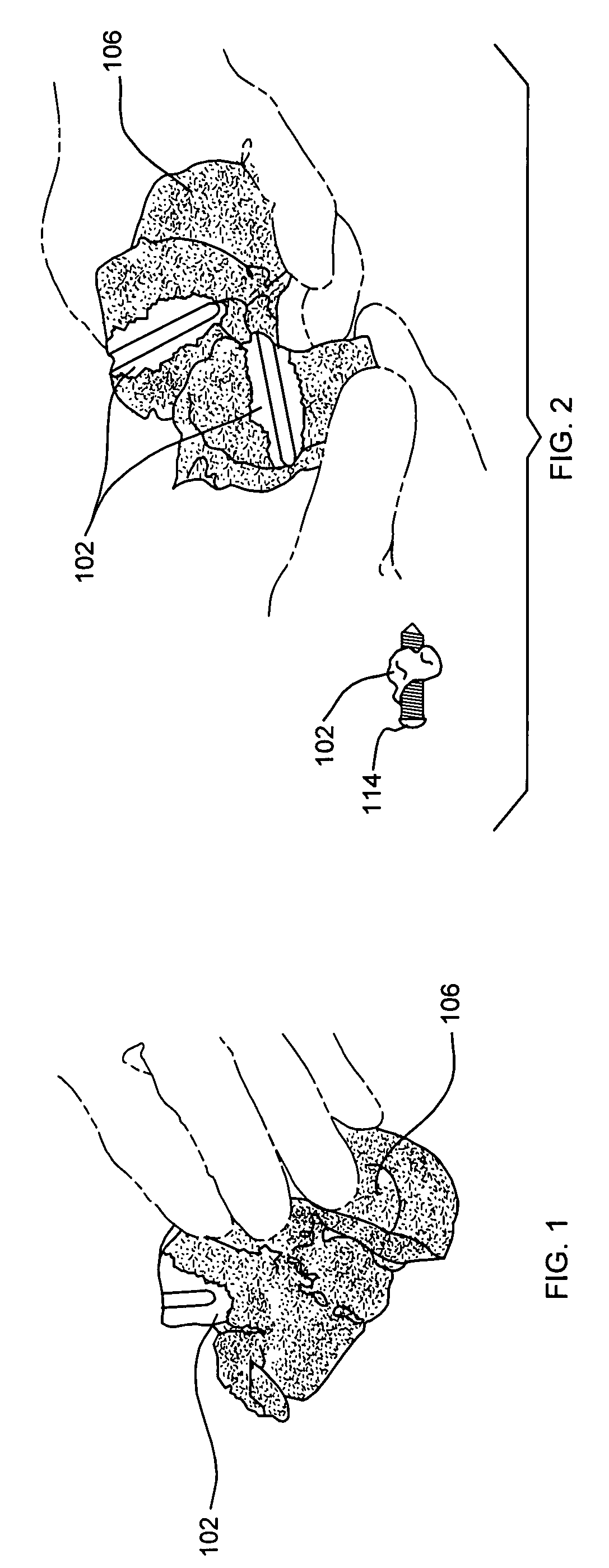
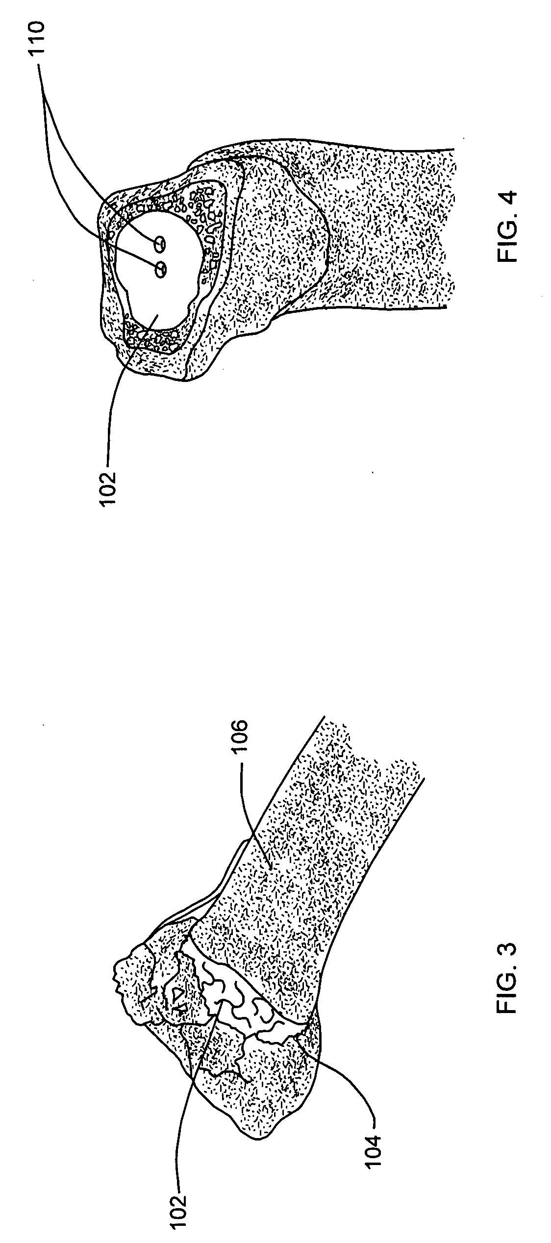
[0094] PCL material was injected into a 4.2 mm drill hole in a cadaver and a 5 mm locking screw was placed therein. The material was injected through an injection device as described above and was used for injection set at 80° C. Good perfusion into the relatively dense cancellous bone can be seen in FIGS. 1 and 2.

example 3

[0095] A finite element analysis (FEA) was performed on a construct simulating a stainless steel screw in cancellous bone with an offset load. The modulus of each of the materials was assigned as reported in Table 1, above. Three conditions were tested in the FEA simulation:

[0096] 1) Ø8 mm stainless steel screw in cancellous bone block without augmentation

[0097] 2) 3 mm of PMMA augmentation around screw

[0098] 3) 3 mm of PCL augmentation around screw

[0099] The screw was rigidly constrained on the proximal end and a unit load was placed on the cancellous bone at the distal end. The maximum stress at the screw to bone interface was assessed with the results shown in FIG. 13.


PUM

PropertyMeasurementUnit
densityaaaaaaaaaa
resportion timeaaaaaaaaaa
Tmaaaaaaaaaa

Abstract

A method for augmenting a tissue including introducing into the tissue a first thermoplastic material at a first condition; treating the first thermoplastic material to achieve a second condition that includes an at least partially crystalline skin; and introducing a second material into the tissue whereby the first thermoplastic material and the second material are contained by the at least partially crystalline skin. Also a method of fracture reduction in a tissue including exposing to gamma radiation a mass of polycaprolactone characterized by a first shape; heating the mass of irradiated polycaprolactone above its melting temperature; introducing the heated mass of polycaprolactone into the tissue annulus to deform it from the first shape; allowing the material to return to the first shape.

Description

CROSS REFERENCE TO RELATED APPLICATION [0001] This application is based off and claims priority to U.S. Provisional Patent application No. 60 / 799,283, filed May 10, 2006, the content of which is hereby incorporated herein by reference in its entirety.INCORPORATION BY REFERENCE [0002] Each and every reference cited herein is hereby incorporated by reference as if set forth in its entirety herein. TECHNICAL FIELD OF THE INVENTION [0003] Generally, the present invention relates to methods and materials for augmenting and repairing bone. BACKGROUND OF THE FIELD OF THE INVENTION [0004] Current standards for attaching implants such as plates to bones often constitute screws in a plurality of shapes. The purpose of these screws is to transfer the load from one bone fragment to the plate or nail and back to a secondary bone fragment. [0005] To ensure this load transfer, the screws must have a good connection in the bone and the plate. The connection between the plate and the screw can be ac...

Claims


Application Information

Patent Timeline
Patent Type & Authority Applications(United States)
IPC IPC(8): A61K47/30A61B17/88A61F2/02
CPCA61B17/1615A61B17/686A61K9/0024A61B17/8805A61B17/8855A61B17/7097A61P19/08A61P29/00A61P31/00A61B17/68A61B17/7098A61B17/84A61B17/8802A61B17/8833B29C35/08B29C65/70B29C70/84B29C73/02B29C2035/085B29K2067/00B29K2711/06B29L2031/7532
Inventor KERR, SEAN H.RECBER, ALI CEM
Owner DEPUY SYNTHES PROD INC
Why Eureka
Try Eureka