On-chip receiver eye finder circuit for high-speed serial link

a receiver circuit and serial link technology, applied in the direction of speed/acceleration/shock measurement devices, instant pulse delivery arrangements, recording information storage, etc., can solve the problem of reducing the number of additional pins needed, adding too much extra load to the equalizer output, and requiring additional cost and power consumption for the receiver circuit being tested. to achieve the effect of minimizing the number of additional pins

Active Publication Date: 2008-01-03
AVAGO TECH INT SALES PTE LTD
View PDF24 Cites 21 Cited by
  • Summary
  • Abstract
  • Description
  • Claims
  • Application Information

AI Technical Summary

Benefits of technology

[0010]Accordingly, an aspect of the present invention is to provide an eye pattern finder diagnostic circuit of the kind used for a high-speed serial link receiver that resides on the same chip housing the receive equalizer, minimizing the number of additional pins needed.

Problems solved by technology

However, in the art such eye pattern detection circuits are not located in the same chip as the receive equalizer but are off-chip.
Driving the signal off-chip also often results in the signal being measured being degraded.
However, the system of clock interpolation and the two additional capture latches add too much extra loading to the equalizer output, as well as requiring two full phase interpolators, one for each latch, to control the clocks.
This requires additional cost and power consumption to the receiver circuit being tested.

Method used


Image

  • On-chip receiver eye finder circuit for high-speed serial link
  • On-chip receiver eye finder circuit for high-speed serial link
  • On-chip receiver eye finder circuit for high-speed serial link

Examples


Embodiment Construction

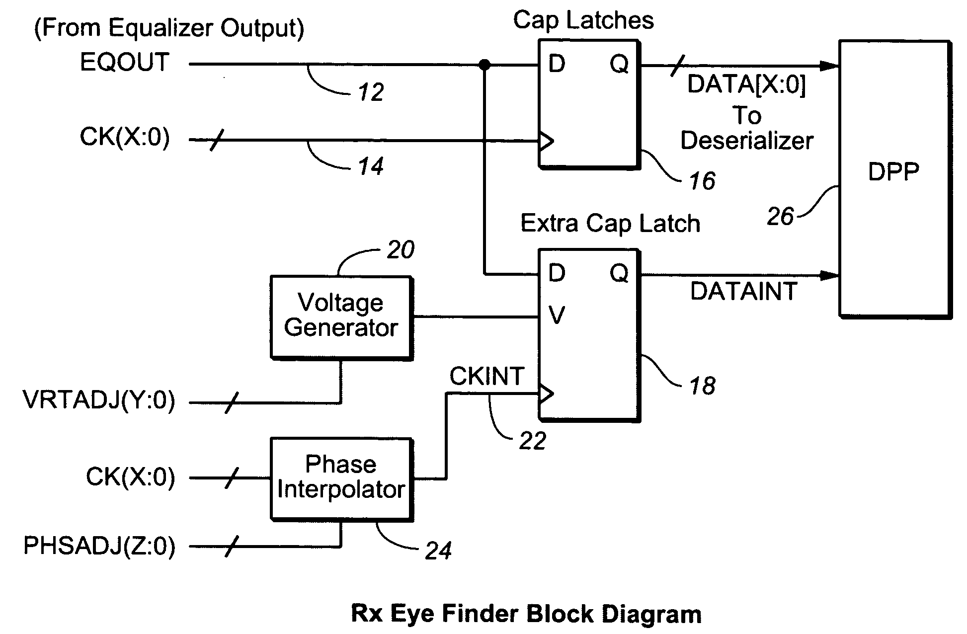
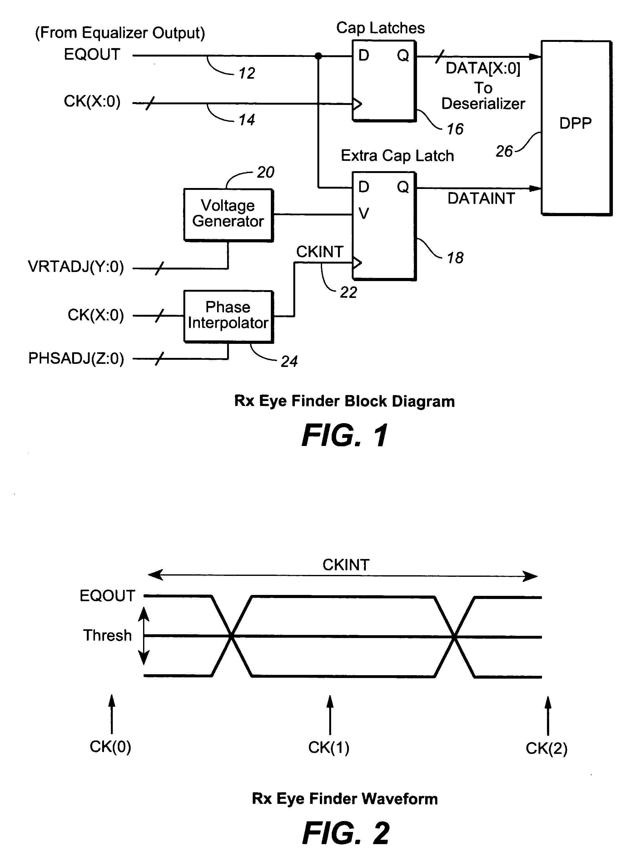
[0022]The method and apparatus of the present invention comprises the circuit shown in FIG. 1, a block diagram detailing the receiver eye finder diagnostic circuit that lies in-line and downstream of the equalizer circuit in a high-speed serial link receiver having one or more capture latches.

[0023]In FIG. 1, there is shown a signal line 12 labeled EQOUT, which is digital output from an equalizer (not shown), and a clock signal line 14 labeled CK(X:0), which is the digital clock signal line leading to a first or existing capture latch (flip-flop) 16, which may be a D-type latch (delay flip-flop) having output 0 when the flip-flop is strobed. The output of Q is digital data [X:0], X-bits / word long, that may lead to a deserializer when the present invention is employed in a high-speed serial link. The lines EQOUT, CK(X:0), DATA[X:0] and the capture latch 16 are circuitry components of a receiver found on a single integrated circuit in a high-speed serial link.

[0024]FIG. 1 shows the ad...


PUM


Abstract

In a high-speed serial link, an eye finder diagnostic circuit has improved performance by being on-chip with the existing capture latch(es) of a receive equalizer. The eye finder circuit employs an additional capture latch with its input tied to the same input node as the existing capture latch(es) of a receive equalizer. The additional capture latch has a clock input and reference voltage input. The clock input is adjusted through a phase interpolator (or variable delay line) while the reference voltage input is adjusted by a voltage generator. A digital post processing circuit then compares the output of the additional capture latch with the output of the other existing capture latch(es), in order to determine the receive eye opening. The horizontal eye opening is measured by changing the phase of the additional capture latch through the phase interpolator, while the vertical eye opening is measured by changing the reference voltage of the voltage generator of the additional capture latch. The eye finder circuit, being on-chip and in-line with existing capture latch(es), employs a minimum of power, minimum of area, and minimizes the extra loading to the existing equalizer output.

Description

CROSS-REFERENCE TO RELATED APPLICATIONS[0001][none]BACKGROUND OF THE INVENTION[0002]1. Field of Invention[0003]The present invention relates generally to the field of diagnostic test circuitry for high-speed serial links.[0004]2. Description of Related Art[0005]In telecommunications, an eye pattern is a display on an oscilloscope in which a pseudorandom digital data signal is repetitively sampled and applied to the vertical input of the oscilloscope, while the data rate is used to trigger the horizontal sweep. The eye pattern is so called because when the signal sampled is in NRZ (Non-Return-To-Zero) code, the pattern resembles eyes between a pair of rails. Since a receive waveform can be degraded during transmission due to intersymbol interference, jitter, crosstalk, noise and the like, system performance can be derived by analyzing the eye pattern. An open eye pattern corresponds to minimal signal distortion, while a closed eye pattern implies distortion.[0006]Diagnostic circuits ...

Claims


Application Information

Patent Timeline
Patent Type & Authority Applications(United States)
IPC IPC(8): G01R31/28
CPCG01R31/3171
Inventor WINDLER, PETERLIM, RICHARD
Owner AVAGO TECH INT SALES PTE LTD
Why Eureka
Try Eureka