Smart antenna array over fiber

a fiber optic and antenna technology, applied in the field of mobile communication, can solve the problems of limiting service availability, substantially higher cost, and not allowing for uniform pilot sector coverage, and achieve the effect of improving performance and signal quality

Inactive Publication Date: 2008-01-10
POWERWAVE TECH INC
View PDF20 Cites 126 Cited by
  • Summary
  • Abstract
  • Description
  • Claims
  • Application Information

AI Technical Summary

Benefits of technology

[0012]In view of the foregoing, the following system and methods provide improved performance and signal quality for wireless communications systems with smart antenna arrays.

Problems solved by technology

In practice, when cell site sectorization has been implemented, the signal-to-interference ratio limits the service availability.
A 6-sector solution improves capacity even further, but at a substantially higher cost.
This coverage shift occurs due to RF beam forming, which does not allow for uniform pilot sector coverage.
Non-uniform pilot sector coverage typically results in hard hand offs and cell blockage.
Uncompensated differences in phase, amplitude and delays between each transceiver—antenna module will lead to degraded SA performance.
However, such an approach cannot avoid long-term degradation due to component drift and aging.
In urban environments, finding such a clear LOS location can be very difficult.
As described above, both conventional methods require auxiliary equipments and external test signal generation, and require down time from normal revenue operation.

Method used


Image

  • Smart antenna array over fiber
  • Smart antenna array over fiber
  • Smart antenna array over fiber

Examples


Embodiment Construction

[0044]The present invention will now be described, by way of example, the best mode contemplated by the inventors for carrying out the present invention, in reference with the accompanying drawings. It shall be understood that the following description, together with numerous specific details, may not contain specific details that have been omitted as it shall be understood that numerous variations are possible and thus will be detracting from the full understanding of the present invention. It will be apparent, however, to those skilled in the art, that the present invention may be put into practice while utilizing various techniques.

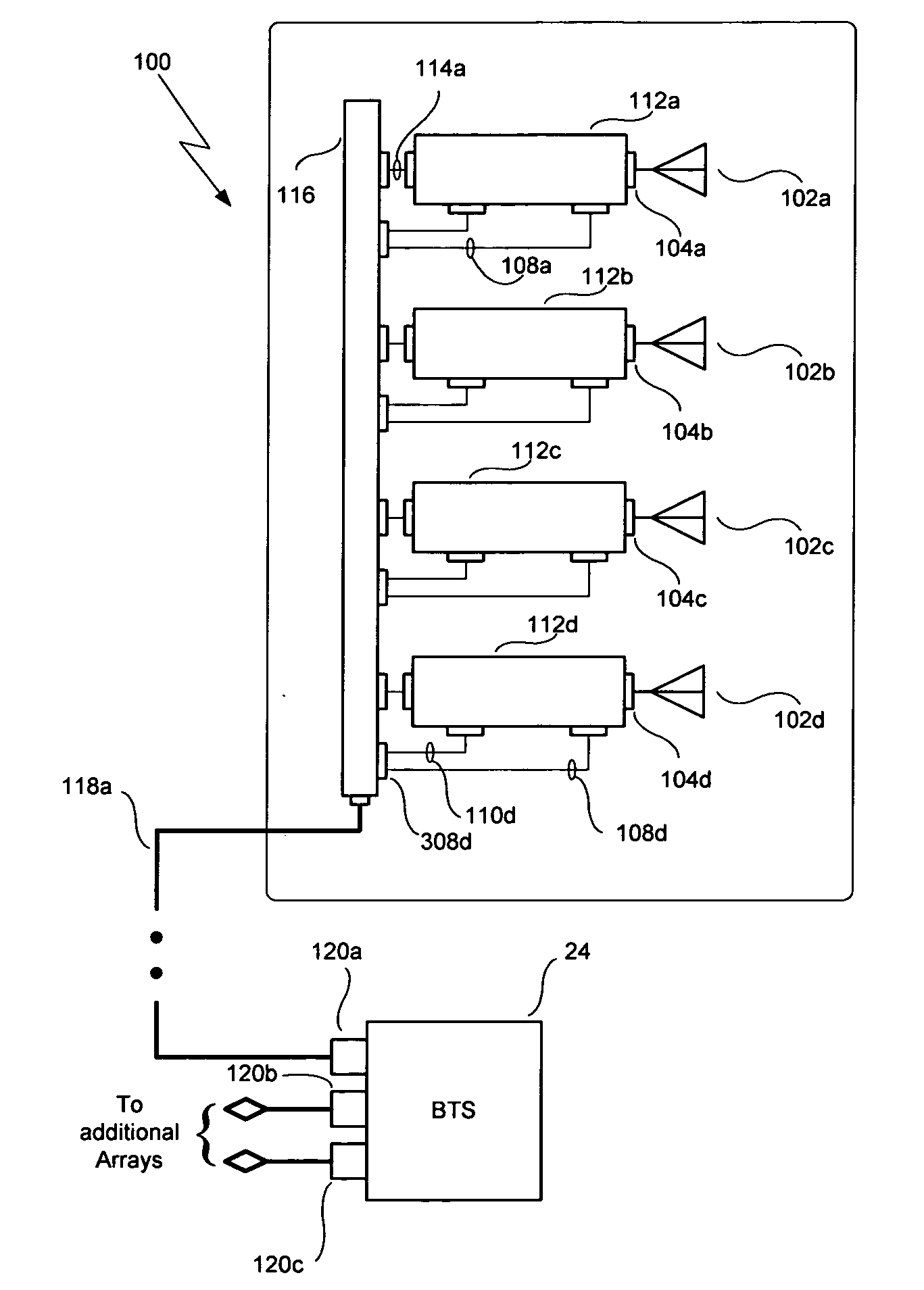
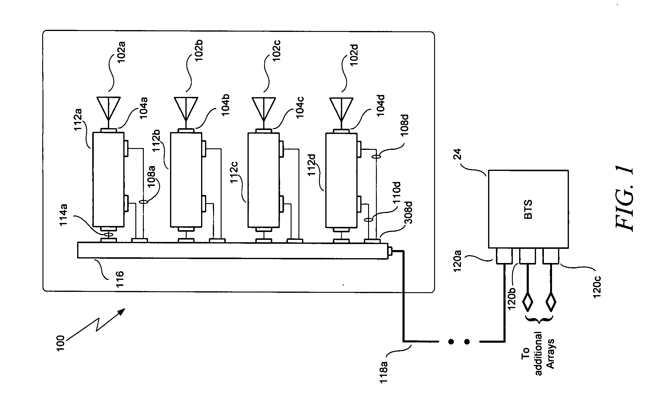
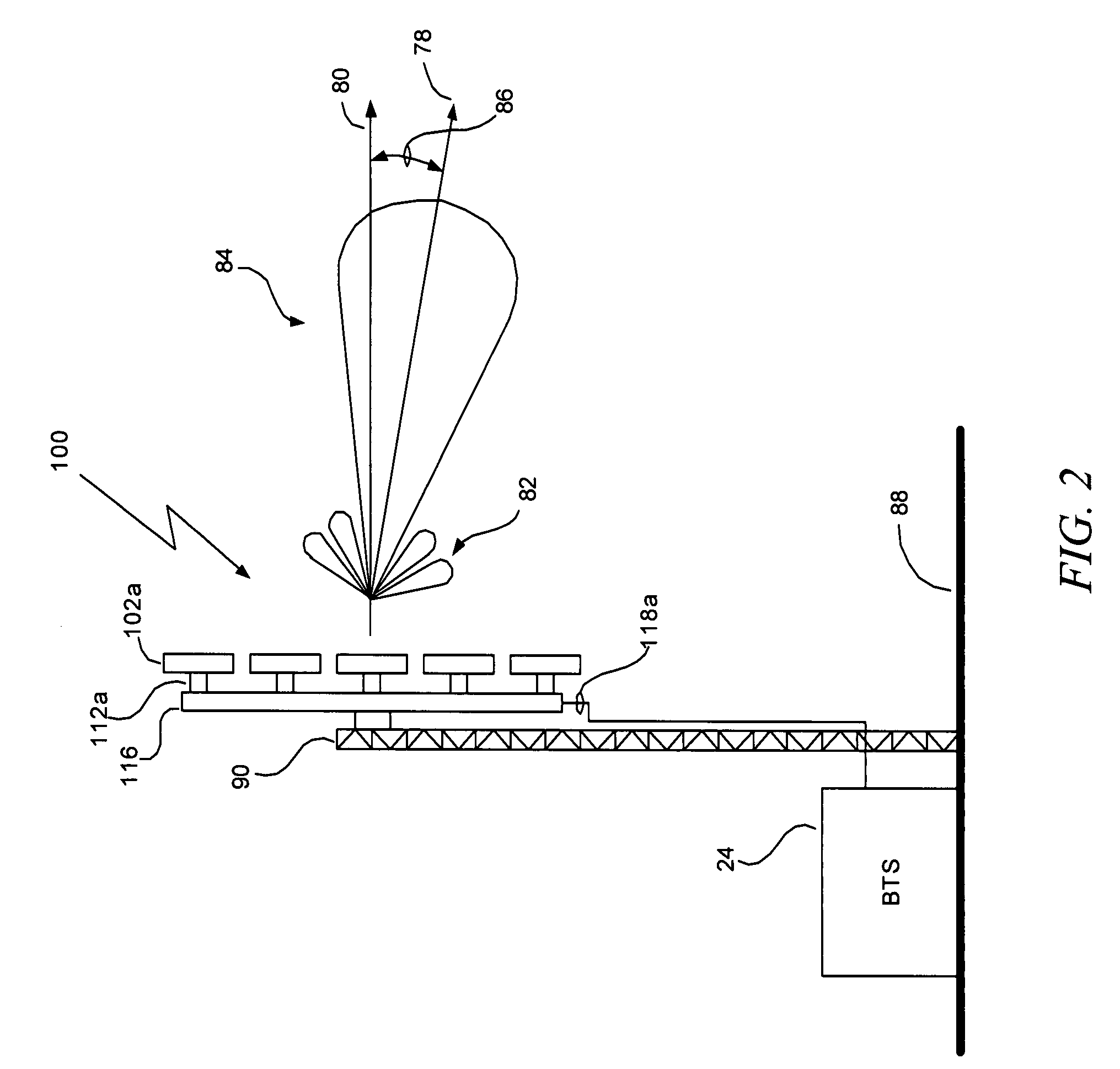
[0045]Disclosed herewith is a smart antenna system and method for calibrating a smart antenna array having a plurality of Transmit—Receive Modules (TRMs). (As used herein a Transmit—Receive Module, or TRM, includes at least a transmit or a receive path but may preferably include both.) In accordance with a preferred embodiment of the present invention,...


PUM


Abstract

A smart antenna system includes a plurality of antennas, a plurality of Transmit—Receive Modules (TRMs) coupled respectively to the plurality of antennas, and a beam steering module coupled to the plurality of TRMs and providing radiation beam steering for the plurality of TRMs. The beam steering module includes a pilot generator for generating a pilot signal and providing it to the TRMs to calibrate a receive (RX) reference plane. The pilot signal is injected at a first location before the receiver section into the RX path, and the pilot signal is sampled at a second location after the receiver section. The TRMs and the beam steering module can also be used to calibrate a transmit (TX) reference plane by sampling output signals from the TRMs. The output signals have a pilot signal component, and are sampled at the first location in the TX path after the transmitter section.

Description

CROSS-REFERENCE TO RELATED APPLICATION[0001]The present application claims priority under 35 USC section 119(e) to U.S. Provisional Patent Application Ser. No. 60 / 812,820, filed Jun. 12, 2006, the disclosure of which is herein incorporated by reference in its entirety.BACKGROUND OF THE INVENTION[0002]1. Field of the Invention[0003]The invention relates generally to the mobile communication field. More specifically, the invention relates to systems and methods related to radio beam forming by a smart antenna.[0004]2. Description of the Prior Art and Related Information[0005]Since the introduction of cellular service in the early 1980's, the mobile communications networks have led to an increasing demand for enhancing efficiency and performance characteristics of the network. Increasing network capacity at peak usage hours, enhanced data rates for mobile data devices, signal quality, network coverage, and reduction in harmful interference to collocated wireless services are important ...

Claims


Application Information

Patent Timeline
Patent Type & Authority Applications(United States)
IPC IPC(8): H01Q3/00H04Q7/20
CPCH01Q1/246H01Q21/0025H01Q3/2676H01Q3/267
Inventor VASSILAKIS, BILLHUNTON, MATTHEW J.RABINOVICH, ALEXANDER
Owner POWERWAVE TECH INC
Why Eureka
Try Eureka