
Reducing packet loss for a packet data service during congestion in a transport network

Active Publication Date: 2008-01-10
RPX CORP
View PDF11 Cites 34 Cited by
  • Summary
  • Abstract
  • Description
  • Claims
  • Application Information

AI Technical Summary

Benefits of technology

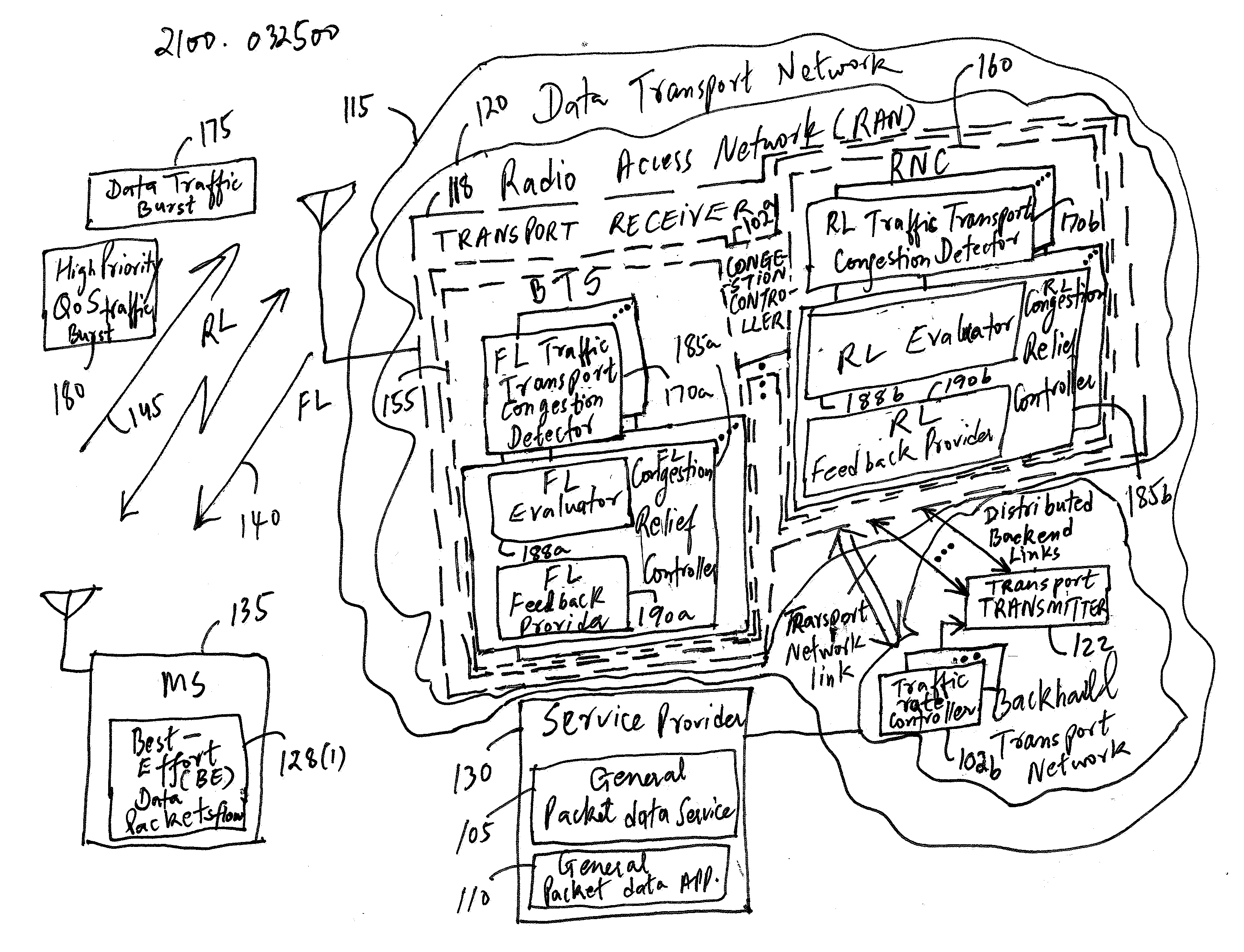
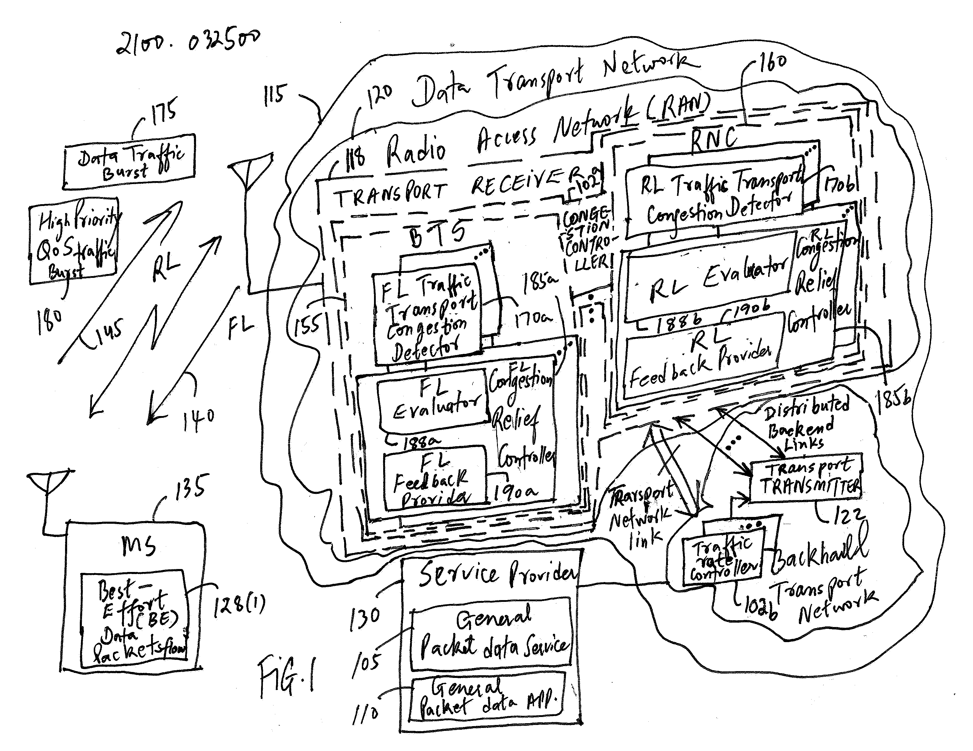
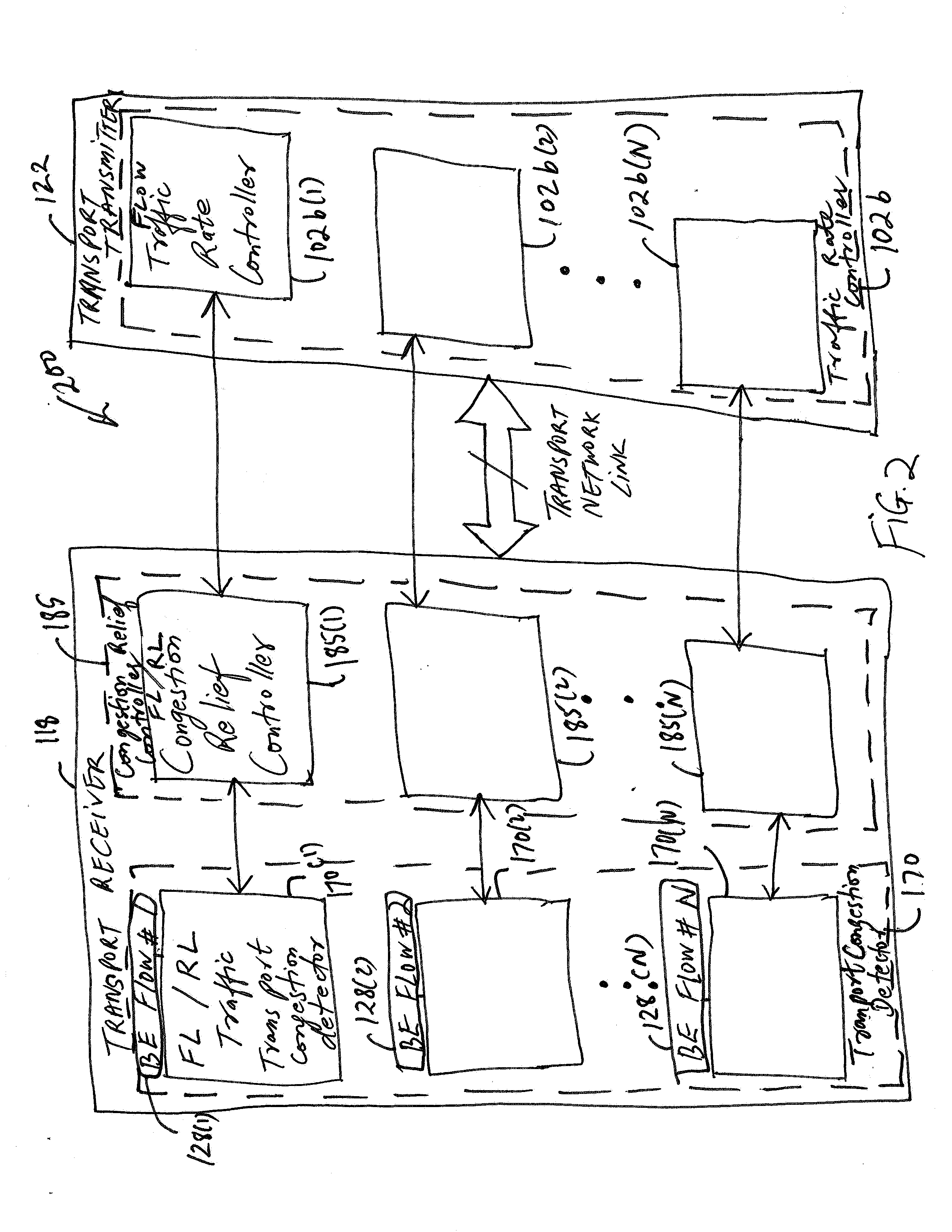
[0013]In one illustrative embodiment of the present invention, a method of reducing packet loss for a packet data service during congestion in a data transport network is provided. The method comprises measuring a packet loss rate over a time period in one or more flows of data traffic packets associated with the packet data service to determine whether the one or more flows of data traffic packets are experiencing a

Problems solved by technology

However, an increasing number of packet data services, and other services, impose user demands on the data network usage for transportation of service traffic.
That is, one of the resource bottlenecks that may impact service performance includes backhaul resources.
Although performance of such a service may suffer a gradual degradation with a prolonged packet delay and / or increases in packet loss, a general packet data service may usually be treated with a relatively lower priority than Quality of Service (QoS) desiring services, such as real-time multi-media applications.
Furthermore, since many general packet data applications may typically involve bursty traffic, the likelihood of the best effort data packets experience a buffer overflow during network congestion is far greater than other types of traffic.
A recovery process, on the other hand, takes much longer time.
As a result, TCP-based data application performance is very sensitive to packet loss during the network congestion periods.
Accordingly, when a data transport network is temporarily congested due to traffic burstiness (e.g., data traffic burstiness or higher priority QoS traffic burstiness), network packet loss from the best-effort data traffic and TCP time-out may cause a significant application performance degradation.
This approach has several drawbacks for a QoS system:1. With different QoS per-hop-behavior configurations in the transport nodes along the transport path, it is difficult to derive a particular QoS class traffic performance from the aggregate packet loss.2. By using only an aggregate traffic performance metric, it is difficult to determine the level of traffic reduction desired in a bursty traffic mix scenario.

Method used


Image

  • Reducing packet loss for a packet data service during congestion in a transport network
  • Reducing packet loss for a packet data service during congestion in a transport network
  • Reducing packet loss for a packet data service during congestion in a transport network

Examples


Embodiment Construction

[0020]Illustrative embodiments of the invention are described below. In the interest of clarity, not all features of an actual implementation are described in this specification. It will of course be appreciated that in the development of any such actual embodiment, numerous implementation-specific decisions may be made to achieve the developers′ specific goals, such as compliance with system-related and business-related constraints, which will vary from one implementation to another. Moreover, it should be appreciated that such a development effort might be complex and time-consuming, but may nevertheless be a routine undertaking for those of ordinary skill in the art having the benefit of this disclosure.

[0021]Generally, a method is provided for reducing packet loss for a packet data service during congestion in the data transport network including an access network, for example, a Radio Access Network (RAN) by controlling congestion of Best Effort (BE) packets. As used herein, in...


PUM


Abstract

A method and an apparatus for reducing packet loss for a packet data service during congestion in a transport network are provided. The method comprises measuring a packet loss rate over a time period in one or more flows of data traffic packets associated with the packet data service to determine whether the one or more flows of data traffic packets are experiencing a variation in a desired traffic performance level at a particular time duration during the congestion in the time period. The method further comprises triggering a request to reduce a flow rate of at least one of the one or more flows of data traffic packets based on the packet loss rate if the at least one of the one or more flows of data traffic packets experiences the variation in the desired traffic performance level. By using a distributed transport congestion control, for example, only such Best Effort data traffic packet flows that generate bursty traffic at a specific moment of congestion sense the congestion and thus trigger an associated rate reduction action. However, other flows that do not experience the congestion may not be affected.

Description

FIELD OF THE INVENTION[0001]This invention relates generally to telecommunications, and more particularly, to wireless communications.DESCRIPTION OF THE RELATED ART[0002]Wireless communications systems or mobile telecommunication systems typically provide different types of services to different users or subscribers of wireless communication devices. The wireless communication devices may be mobile or fixed units and situated within a geographic region across one or more wireless networks. The users or subscribers of wireless units or communication devices, such as mobile stations (MSs) or access terminals or user equipment may constantly move within (and outside) particular wireless networks.[0003]A wireless communications system generally includes one or more base stations (BSs) that can establish wireless communications links with wireless units. Each wireless unit has an active set, which comprises a set of base stations with which it may communicate. Base stations may also be r...

Claims


Application Information

Patent Timeline
IPC IPC(8): H04J1/16
CPCH04L47/10H04L47/12H04L47/14H04L47/24Y02B60/31H04L47/32H04W28/04H04W28/08H04W28/22H04L47/263H04W28/0252H04W28/10Y02D30/50H04W8/04
Inventor WANG, XINYANG, YANGZHU, LILY H.
Owner RPX CORP
Learn More