Mixer with dynamic intermediate frequency for radio-frequency front-end and method using the same

a radio-frequency front-end and dynamic intermediate frequency technology, applied in the field of communication system and method, can solve the problems of large area occupation of the rf front-end circuitry, self-mixing phenomenon, and limiting the sensitivity of the receiver, so as to reduce the size of the circuitry, improve the efficiency of the radio-frequency front-end, and eliminate phase noise of the amplified received signal

Inactive Publication Date: 2008-01-10
MEDIATEK INC
View PDF31 Cites 7 Cited by
  • Summary
  • Abstract
  • Description
  • Claims
  • Application Information

AI Technical Summary

Benefits of technology

[0009]Another object of the present invention is to provide a mixer apparatus with a dividing unit to provide a plurality of frequency signals to the first and the second mixer units to improve the efficiency of the radio-frequency front-end.
[0010]Still one object of the present invention is to provide a radio-frequency front-end with simplified mixer architecture to reduce the size of the circuitry and for low voltage and power consumption.
[0011]According to the above objects, the present invention sets forth a radio-frequency front-end with single-stage mixer units having dynamic intermediate frequency (IF) and method thereof. The radio-frequency front-end comprises a band-pass filter, an amplifier, a first mixer unit and a second mixer unit. The band-pass filter receives a first radio frequency (RF) signal to suppress the unwanted signal that is out of the wanted frequency band to generate a second RF signal. The amplifier is connected to the band-pass filter to amplify the second RF signal and output a third RF signal, denoted by SRF. The first mixer unit coupled to the amplifier is used to mix the third RF signal (SRF) with a first frequency signal (S1) to down convert the third RF signal (SRF) to an intermediate frequency (IF) and outputs an IF signal, denoted by SIF. The second mixer unit is connected to the first mixer unit in a cascode configuration and has an I-channel mixer and a Q-channel mixer to transform IF signal (SIF) to an I-channel signal (SI) and a Q-channel signal (SQ). Note that the single-stage structure with cascode configuration can improve circuit noise. Further, some kind of active or passive components, such as coupling capacitors, between the first and the second mixer units in the single-stage structure are removed to reduce the size of the first and the second mixer units within the radio-frequency front-end circuitry. Moreover, such a cascode configuration benefits lower power consumption on the radio-frequency front-end.
[0015]Next, the radio frequency signal at a carrier frequency is mixed with the first frequency signal to down convert the RF signal to an intermediate frequency (IF) and output an IF signal using a first mixer. The frequency of the first frequency signal is preferably smaller than an oscillator signal inputted into the dividing unit to eliminate phase noise of the amplified received signal. Finally, the IF signal is mixed with the second and the third frequency signals using a second mixer to output an I-channel signal and a Q-channel signal at baseband, respectively, where the first mixer and the second mixers are connected in a cascode configuration with the second mixer.
[0016]The advantages of the present invention include: (a) providing mixer architecture in a cascode configuration to dynamically adjust the intermediate frequency in a radio-frequency front-end; (b) providing simplified mixer architecture with a dividing unit to improve the efficiency of the radio-frequency front-end; and (c) reducing the size of the circuitry in the radio-frequency front-end.

Problems solved by technology

However, improper isolation between local oscillator (LO) and RF signals is induced, thereby producing a self-mixing phenomenon, as shown in FIG. 1.
However, before entering the mixer 108, the RF signal 104 has been mixed with the LO signal and thus may saturates the baseband amplifiers 110, thereby limiting the receiver sensitivity.
However, a first mixer 202, second mixer 204 and local noise amplifier (LNA) 206 are inductor-based loads, resulting in a large amount area occupation on the RF front-end circuitry.
This approach also has much more power consumption due to the additional components.

Method used


Image

  • Mixer with dynamic intermediate frequency for radio-frequency front-end and method using the same
  • Mixer with dynamic intermediate frequency for radio-frequency front-end and method using the same
  • Mixer with dynamic intermediate frequency for radio-frequency front-end and method using the same

Examples


Embodiment Construction

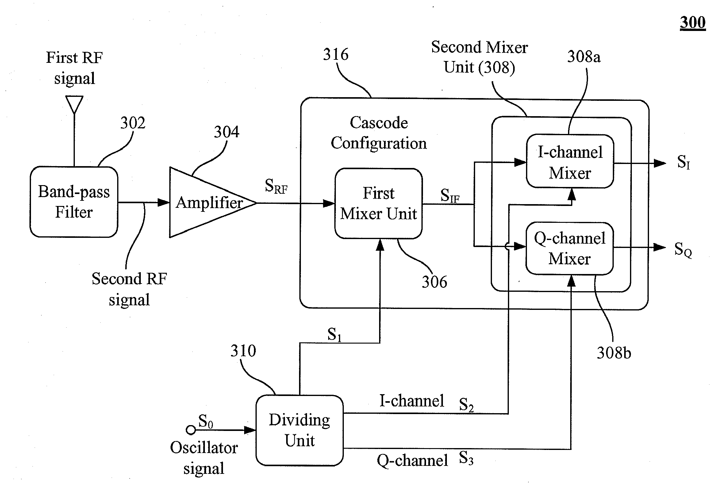
[0024]The present invention is directed to the simplified mixer architecture with dynamic intermediate frequency used in a radio-frequency (RF) front-end to actively adjust the intermediate frequency by the first and the second mixer units in a cascode configuration. A dividing unit can be further employed to receive an oscillator signal to provide a first, a second, and a third frequency signals to the first and the second mixer units. Moreover, the radio-frequency front-end with simplified mixer architecture can reduce the size of the circuitry. The mixer architecture of the present invention is applicable to any kind of transceivers including receivers and transmitters, preferably for direct conversion receivers.

[0025]Referring to FIG. 3, a schematic block diagram of a radio-frequency front-end with mixers according to one embodiment of the present invention is shown. The radio-frequency front-end 300 comprises a band-pass filter 302, an amplifier 304, a first mixer unit 306 and ...


PUM


Abstract

A mixer with dynamic intermediate frequency in a RF front-end to dynamically adjust the intermediate frequency and method thereof are described. The radio-frequency front-end comprises a band-pass filter, an amplifier, a first mixer unit and a second mixer unit. The band-pass filter receives first RF signal to generate second RF signal. The amplifier amplified the second RF signal and output third RF signal (SRF). The first mixer unit is used to mix the third RF signal (SRF) with first frequency signal (S1) to down convert the third RF signal (SRF) to an intermediate frequency (IF) and outputs an IF signal (SIF). The second mixer unit is connected to the first mixer unit in a cascode configuration and has I-channel and Q-channel mixers to transform IF signal (SIF) to an I-channel signal (SI) and a Q-channel signal (SQ). The radio-frequency front-end further comprises a dividing unit for receiving an oscillator signal (S0) to generate the first, the second and the third frequency signals (S1, S2, and S3) such that the frequency of the first frequency signal (S1) substantially equals the frequency of the oscillator signal (S0) divided by two's power of a first non-negative integer (N1), the frequency of the second and the third frequency signals (S2, and S3) substantially both equals the frequency of the oscillator signal (S0) divided by two's power of a second non-negative integer (N2), and the second frequency signal (S2) is approximately 90 degree out of phase with respect to the third frequency signal (S3).

Description

FIELD OF THE INVENTION[0001]The present invention generally relates to a communication system and method, and more particularly, to a mixer with dynamic intermediate frequency (IF) used in a radio-frequency (RF) front-end of direct conversion transceiver to dynamically adjust the intermediate frequency and method thereof.BACKGROUND OF THE INVENTION[0002]Currently, there is a great amount of activity to realize low cost transceivers for the wireless communication applications. Examples of communication applications include digital cordless telephones, digital cellular, wireless modems, and wireless personal communication networks. All transceiver architectures routinely employ a mixer in the frequency translation of the most transceivers from the radio frequency to the intermediate frequency (IF) and vice versa.[0003]A kind of receiver topology is called a direct conversion receiver which directly down converts the RF signals into baseband signals. The direct conversion receiver has ...

Claims


Application Information

Patent Timeline
Patent Type & Authority Applications(United States)
IPC IPC(8): H04B1/26
CPCH03D7/1433H03D7/1458H04B1/28H03D7/165
Inventor CHIU, CHINQ-SHIUN
Owner MEDIATEK INC
Why Eureka
Try Eureka