Eureka AIR delivers breakthrough ideas for toughest innovation challenges, trusted by R&D personnel around the world.

Magnetoresistive device, read head and storage having the same

a magnetic sensor and read head technology, applied in the field of magnetic sensors, can solve problems such as insufficient shield effect, and achieve the effects of improving shield characteristic, preventing a degradation of output, and high sensitivity

Inactive Publication Date: 2008-01-17
FUJITSU LTD
View PDF14 Cites 2 Cited by
  • Summary
  • Abstract
  • Description
  • Claims
  • Application Information

AI Technical Summary

Benefits of technology

[0007]A method according to one aspect of the present invention for manufacturing a magnetoresistive device that includes a spin-valve film, and a terminal layer that applies a sense current in a direction of a lamination surface in the spin-valve film, the spin-valve film including a pair of uncoupled ferromagnetic layers, and a non-magnetic metal layer that separates the pair of uncoupled ferromagnetic layers from each other, one of the ferromagnetic layers having a fixed direction of magnetization, and the other of the ferromagnetic layers having a freely variable direction of magnetization includes the steps of forming the terminal layer through sputtering, and preventing a formation of a sharp part on the terminal layer while interrupting the forming step. This manufacturing method executes the preventing step by interrupting the forming step, and prevents a formation of a sharp part from being formed on the terminal layer. Since it becomes difficult to remove a sharp part of the terminal layer after the forming step is completed, the preventing step is conducted in the middle of the forming step. A sharp part is removed from the shield layer that is laminated on the terminal layer when a sharp part is removed from the terminal layer, and the shield characteristic of the shield layer improves.
[0008]The preventing step may include the step of removing, through ion milling, part of the terminal layer that is being formed, while interrupting the forming step, and the method may resume the forming step after the removing step. The part of the terminal layer may be an electrode layer, because the electrode layer is thickest in the terminal layer that includes a lamination of a primary coat, the electrode layer, and a cap layer, and thus can secure a sufficient margin. For example, the removing step may set an angle between an ion beam direction of the ion milling and the direction parallel to the lamination surface to be between a sputtering angle −5° inclusive and the sputtering angle +10° inclusive, the sputtering angle being an angle between a sputtering particle flying direction of the forming step and the direction parallel to the lamination surface. A removal of the sharp part becomes insufficient near the resist outside this range. The removing step may start when a layer of the part of the terminal layer has a thickness between a prospective thickness formed by the forming step −100 Å and the prospective thickness. The removing step may execute the ion milling until a layer of the part of the terminal layer has a thickness between half a prospective thickness formed by the forming step ±100 Å. In this range, the preventing step can secure a sufficient margin, and prevent a formation of the sharp part. The removing step may start the ion milling when the electrode layer of the terminal layer has a thickness between a prospective thickness formed by the forming step −100 Å and the prospective thickness. In this range, the preventing step can secure a sufficient margin, and prevent a formation of the sharp part.
[0009]The preventing step may change a sputtering angle between a sputtering particle flying direction of the forming step and the direction parallel to the lamination surface in the middle of the forming step. Thereby, only a sputtering apparatus can prevent a formation of the sharp part on the terminal part without ion milling. The preventing step may set the sputtering angle greater than the sputtering angle of the forming step. For example, the sputtering angle changes between the sputtering angle of the forming step +5° inclusive and the sputtering angle of the forming step +15° inclusive. In this range, a formation of the sharp part can be prevented. Preferably, the preventing step starts when a layer of part of the terminal layer has a thickness between half a prospective thickness formed by the forming step ±100 Å. In this range, the preventing step can secure a sufficient margin, and prevent a formation of the sharp part.
[0012]A read head according to still another aspect of the present invention includes a magnetoresistive device manufactured by the above manufacturing method or the above magnetoresistive device, a member that supplies a sense current, and a member that reads a signal from an electric resistance of the magnetoresistive device which changes according to a signal magnetic field. This read head has an improved shield characteristic, provides a high sensitivity, and prevents a degradation of an output by reducing the leakage flux. A storage that includes a magnetic head part including the above read head and a write head, and a drive part that drives a magnetic record medium to be recorded and reproduced by the magnetic head part also constitutes another aspect of the present invention.

Problems solved by technology

However, the conventional upper shield layer has a set of plural reflex magnetic domains rather than one reflex magnetic domain, as shown in FIG. 9B, causing an insufficient shield effect.

Method used


Image

  • Magnetoresistive device, read head and storage having the same
  • Magnetoresistive device, read head and storage having the same
  • Magnetoresistive device, read head and storage having the same

Examples


Embodiment Construction

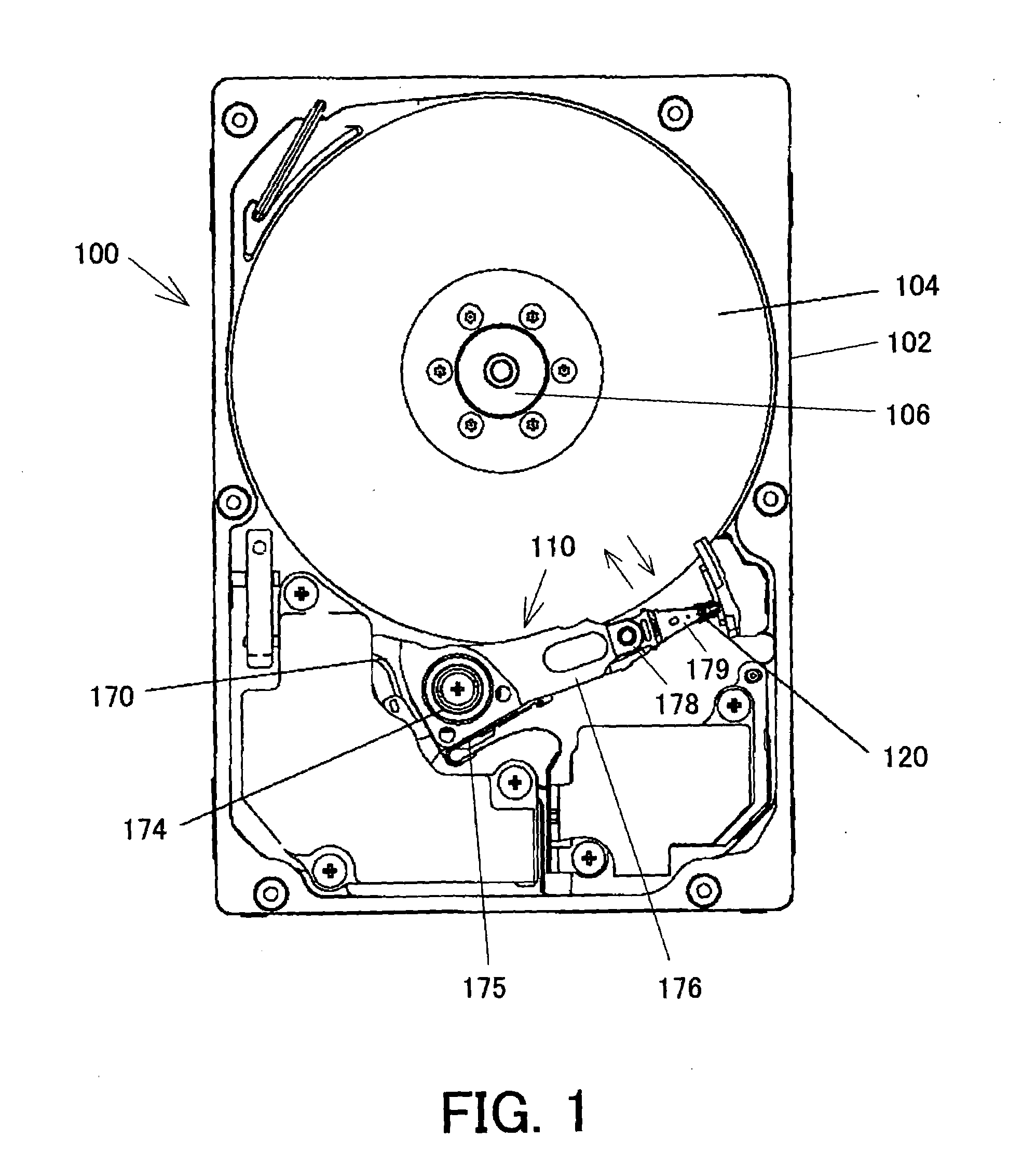
[0025]Referring now to the accompanying drawings, a description will be given of an HDD 100 according to one embodiment of the present invention. The HDD 100 includes, as shown in FIG. 1, one or more magnetic discs 104 each serving as a recording medium, a spindle motor 106, and a head stack assembly (“HAS”) 110 in a housing 102. Here, FIG. 1 is a schematic plane view of the internal structure of the HDD 100.

[0026]The housing 102 is made, for example, of aluminum die cast base, stainless steel, or the like, and has a rectangular parallelepiped shape to which a cover (not shown) that seals the internal space is joined. The magnetic disc 104 has a high surface recording density, such as 100 Gb / in2 or greater. The magnetic disc 104 is mounted on a spindle (hub) of the spindle motor 106 through its center hole of the magnetic disc 104.

[0027]The spindle motor 106 has, for example, a brushless DC motor (not shown) and a spindle as its rotor part. For instance, two magnetic discs 104 are u...


PUM

PropertyMeasurementUnit
angleaaaaaaaaaa
angleaaaaaaaaaa
angleaaaaaaaaaa

Abstract

A method for manufacturing a magnetoresistive device that includes a spin-valve film, and a terminal layer that applies a sense current in a direction of a lamination surface in the spin-valve film, the spin-valve film including a pair of uncoupled ferromagnetic layers, and a non-magnetic metal layer that separates the pair of uncoupled ferromagnetic layers from each other, one of the ferromagnetic layers having a fixed direction of magnetization, and the other of the ferromagnetic layers having a freely variable direction of magnetization includes the steps of forming the terminal layer through sputtering, and preventing a formation of a sharp part on the terminal layer while interrupting the forming step.

Description

[0001]This application claims the right of a foreign priority based on Japanese Patent Application No. 2006-187058, filed on Jul. 6, 2006, which is hereby incorporated by reference herein in its entirety as if fully set forth herein.BACKGROUND OF THE INVENTION[0002]The present invention relates generally to a magnetoresistive device, and more particularly to a CIP-GMR sensor, which is a magnetic sensor that uses not only a spin-valve film that exhibits a giant magnetoresistive (“GMR”) effect, but also a current-in-plane (“CIP”) configuration that applies the sense current parallel to lamination surfaces in the spin-valve film. The present invention is suitable, for example, for a read head for use with a hard disc drive (“HDD”).[0003]Along with the recent spread of the Internet etc., magnetic disc drives that record a large amount of information including still and motion pictures have increasingly been demanded. As the surface recording density increases to meet the demand for the ...

Claims


Application Information

Patent Timeline
Patent Type & Authority Applications(United States)
IPC IPC(8): G11B5/33G11B5/127H04R31/00
CPCG11B5/39Y10T29/49032H04R31/00
Inventor YASUKAWA, TOMOHISA
Owner FUJITSU LTD
Why Eureka
Eureka Blog
Learn More