
Optical Fiber Drawing Apparatus

a drawing apparatus and optical fiber technology, applied in lighting and heating apparatus, instruments, furniture, etc., can solve the problems of too long start-up time or length of start-up fiber, and achieve the effect of stable drawing control, reduced preform elution, and shrinking of the diameter of the optical fiber after drawing

Active Publication Date: 2008-01-24
KOBE STEEL LTD
View PDF2 Cites 8 Cited by
  • Summary
  • Abstract
  • Description
  • Claims
  • Application Information

AI Technical Summary

Benefits of technology

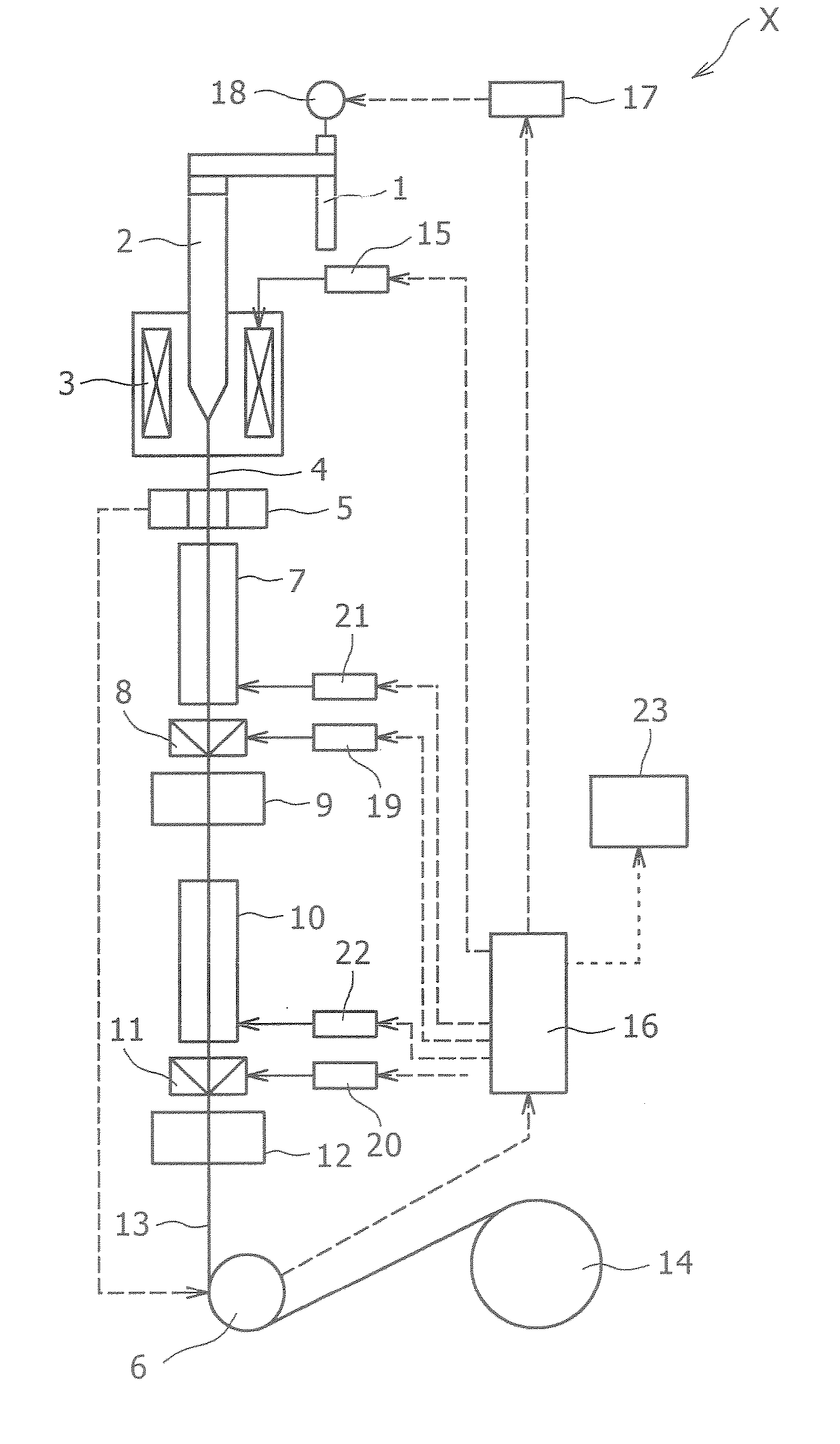
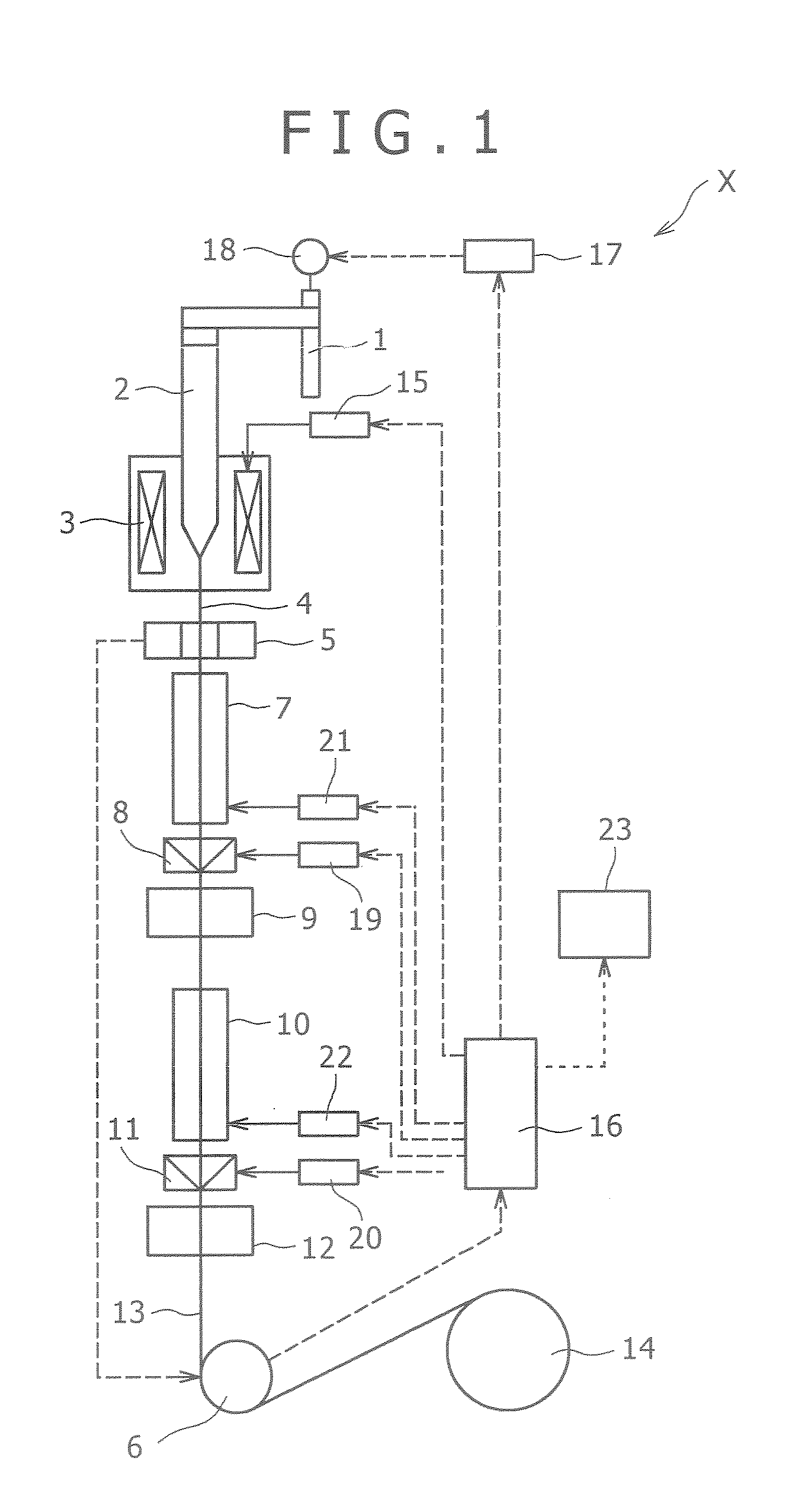
[0021] In concrete, when the variation of the real drawing speed is larger than the target variation of the drawing speed (acceleration is larger), if the feeding speed of the preform is adjusted to decelerate, the elution of the preform is reduced and the diameter of the optical fiber after drawn tends to shrink; accordingly, the real drawing speed is controlled to decelerate so that the diameter thereof becomes a target fiber diameter. On the contrary, when the variation of the real drawing speed is smaller than the target variation of the drawing speed (acceleration is smaller), if the feeding speed of the preform is adjusted to accelerate, the elution of the preform is increased and the real drawing speed is controlled to accelerate. In consequence, the variation of the real drawing speed in the unsteady state operation varies in a realistic form, and a stable drawing control becomes possible which does not generate hunting or overshoot or the like, while reducing a start-up fiber length (or speed increasing timed

Problems solved by technology

And in a start-up state (one example of the unsteady state), for example, if the variation of the real drawing speed (acceleration of the drawing) is too large, there occurs overshoot or hunting while the operation transfers toward the steady state operation, and if the variation of the real drawing speed is too small, the start-up fiber length (or start-up time) becomes too long.

Method used


Image

  • Optical Fiber Drawing Apparatus
  • Optical Fiber Drawing Apparatus
  • Optical Fiber Drawing Apparatus

Examples


Embodiment Construction

[0041] In the optical fiber drawing device relating to the present invention, it is preferable that the arithmetic control unit determines the preform feeding speed Vf(t) by the below formula (i) and adopts it as the speed command signal.

Vf(t)=Vf1+KP(ΔVdt_target−ΔVdt)+KI∫(ΔVdt_target−ΔVdt)dt   (i)

[0042] Here,

[0043] Vf1: base preform feeding speed

[0044]ΔVdt_target: target variation of drawing speed

[0045]ΔVdt: variation of real drawing speed

[0046] KP: variation proportional gain

[0047] KI: variation Integral gain

[0048] dt: integral control cycle

[0049] However, the feedback correction in this invention is not restricted to a combination of the proportional element and the integral element, and one element may be omitted, for example, or a differential element may be added in reverse.

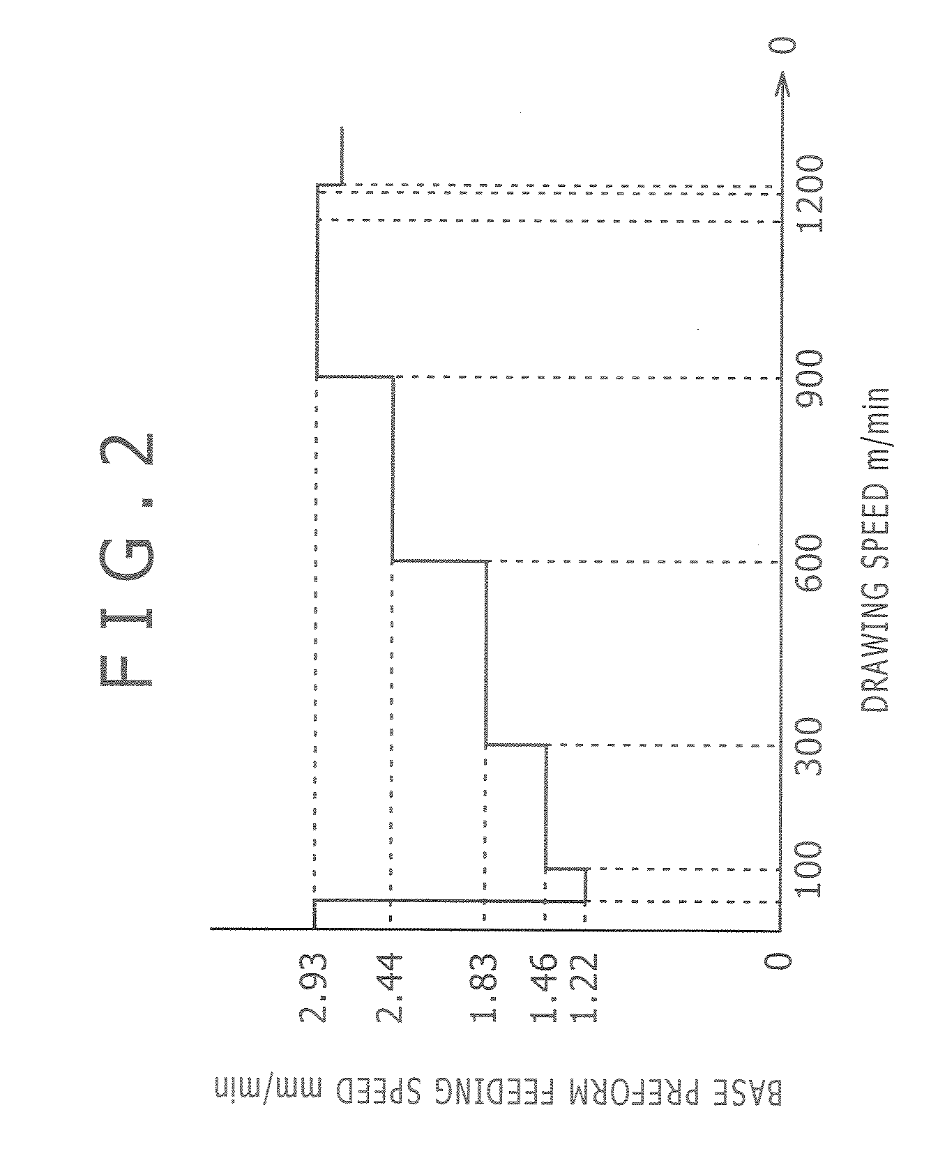
[0050] In the optical fiber drawing device with the above construction, it is further preferable that both the base preform feeding speed and the target variation of the drawing speed are made to b...


PUM

PropertyMeasurementUnit
Speedaaaaaaaaaa
Speedaaaaaaaaaa
Speedaaaaaaaaaa

Abstract

In an optical fiber drawing device of the present invention, as an operational parameters corresponding to the real drawing speed in the duration from the moment of starting the operation of the optical fiber drawing device till the moment of reaching the target drawing speed are extracted from operational parameters stored in a operational parameter storage unit and applied to the optical fiber drawing device. The operational parameters include a base preform feeding speed, a target variation of real drawing speed, a gain multiplied by the speed element related with the variation of the real drawing speed, an operation cycle, a drawing furnace temperature, a coating resin pressure to coat the optical fiber, and flow of cooling gaseous helium, etc. The optical fiber drawing device of the present invention capable of a stable drawing control that does not generate hunting or overshoot or the like, while reducing the start-up fiber length (or speed increasing time) in the unsteady state (transient state) operation of the optical fiber drawing device.

Description

TECHNICAL FIELD [0001] The present invention relates to an optical fiber drawing device that produces an optical fiber from an optical fiber preform. The invention particularly relates to an optical fiber drawing device with the control performance enhanced by varying operational parameters in the operational conditions of the optical fiber drawing device, in response to a momentarily varying drawing speed (real drawing speed during operation of the optical fiber drawing device, and an optical fiber drawing device with a control performance enhanced by continuously varying a target variation of the real drawing speed in response to the drawing speed, and by adjusting a preform feeding speed on the basis of a deviation between the target variation of the real drawing speed and a real variation of the real drawing speed. BACKGROUND ART [0002] In the optical fiber drawing device that produces an optical fiber, generally, the speed of an optical fiber preform being continuously drawn af...

Claims


Application Information

Patent Timeline
IPC IPC(8): C03B37/027G02B6/00G02B6/44
CPCC03B37/0253C03B2205/40C03C25/12C03B2205/72C03B2205/44
Inventor MIYAMOTO, TOSHIYUKIFUKUHARA, NORIOSAKAMOTO, KEIICHIKANEKO, TAKAO
Owner KOBE STEEL LTD
Learn More