
Powder filling apparatus, powder filling method and process cartridge

a filling apparatus and powder technology, applied in the directions of liquid handling, packaging goods types, transportation and packaging, etc., can solve the problems of requiring replacement of the measuring chamber itself, affecting the filling effect, etc., to achieve the effect of short tim

Inactive Publication Date: 2008-01-24
CANON KK
View PDF24 Cites 17 Cited by
  • Summary
  • Abstract
  • Description
  • Claims
  • Application Information

AI Technical Summary

Benefits of technology

The present invention provides a powder filling apparatus and method that can fill powder into containers with high density and in a short period of time. The apparatus includes a pressure hopper with a discharger and a gas inlet positioned above the surface of a powder layer formed by the powder in the pressure hopper. The inside of the pressure hopper is pressurized by leading in gas through the gas inlet, and the powder layer so formed blocks the discharger. The powder layer is then discharged by opening the discharger after the pressurization, utilizing the pressure to fill the powder into the container. The invention also provides a method for filling powder into a filling container divided into a lid and a powder storage part by adjusting the surface shape of the powder in the powder storage part to match the shape of the lid. The invention further relates to a process cartridge for electronic photography filled with a developer by the powder filling method.

Problems solved by technology

However, in the configuration disclosed in Japanese Patent Application Laid-Open No. 2002-293301, as the powder stored in the powder feeding device is packed into the container to be filed after its fluidity is enhanced with the gas, the powder is fluidized more than required, making it difficult to pack the powder into the container to be filled in high density.
The more than required fluidization also causes the filling to take a longer time than otherwise.
H06-062121, as the filled quantity of powder is determined by the size of the measuring chamber, if filling is to be done into the same apparatus more than once in different quantities for instance, the measuring chamber itself will have to be replaced, entailing a heavy burden.
Or if a large quantity of powder is to be filled, this configuration is susceptible to clogging of the filter with the filled powder at the stage of filling the measuring chamber under reduced pressure, making it difficult to load the prescribed quantity.

Method used


Image

  • Powder filling apparatus, powder filling method and process cartridge
  • Powder filling apparatus, powder filling method and process cartridge
  • Powder filling apparatus, powder filling method and process cartridge

Examples


embodiment 1

[0137] Next, a first exemplary embodiment of the invention will be described.

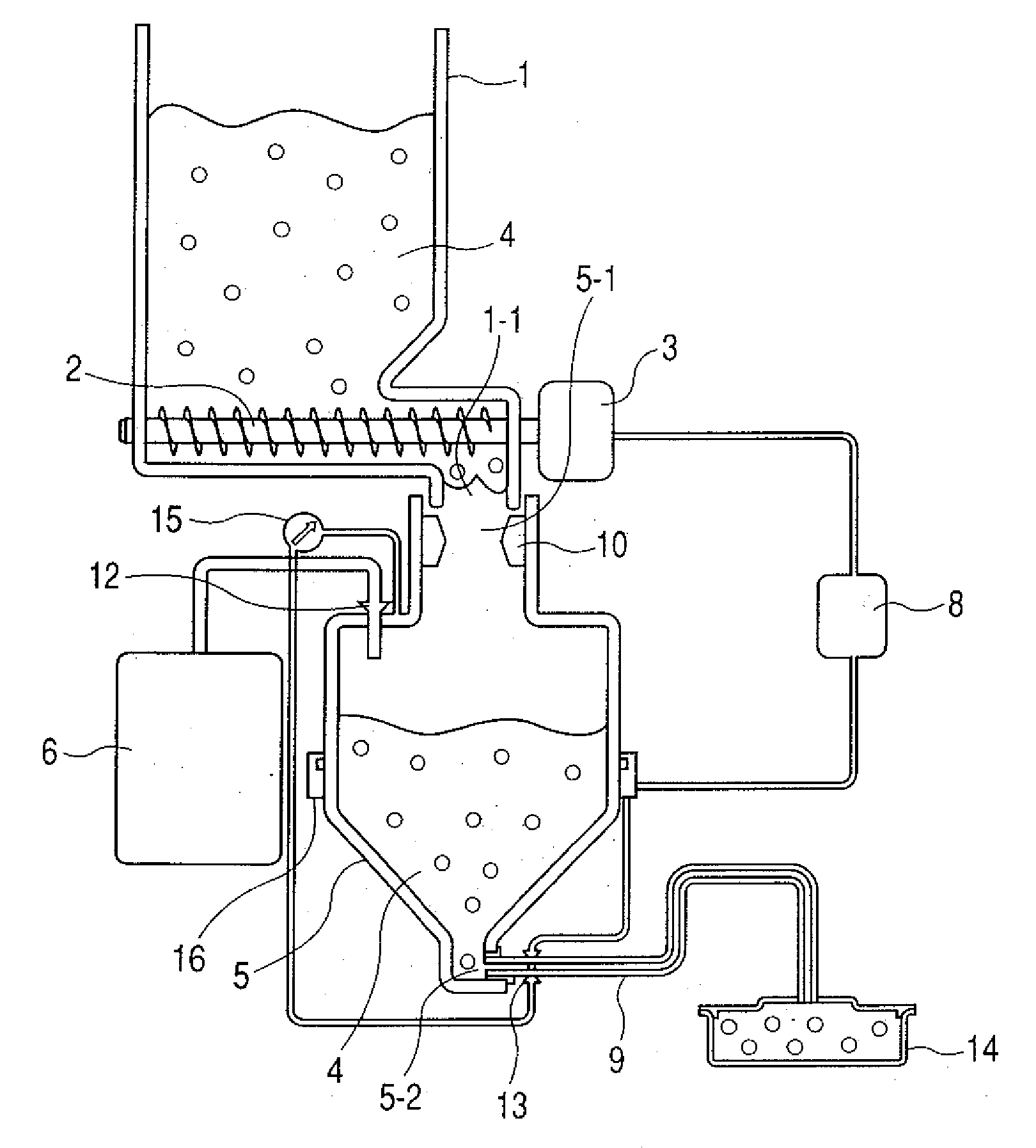
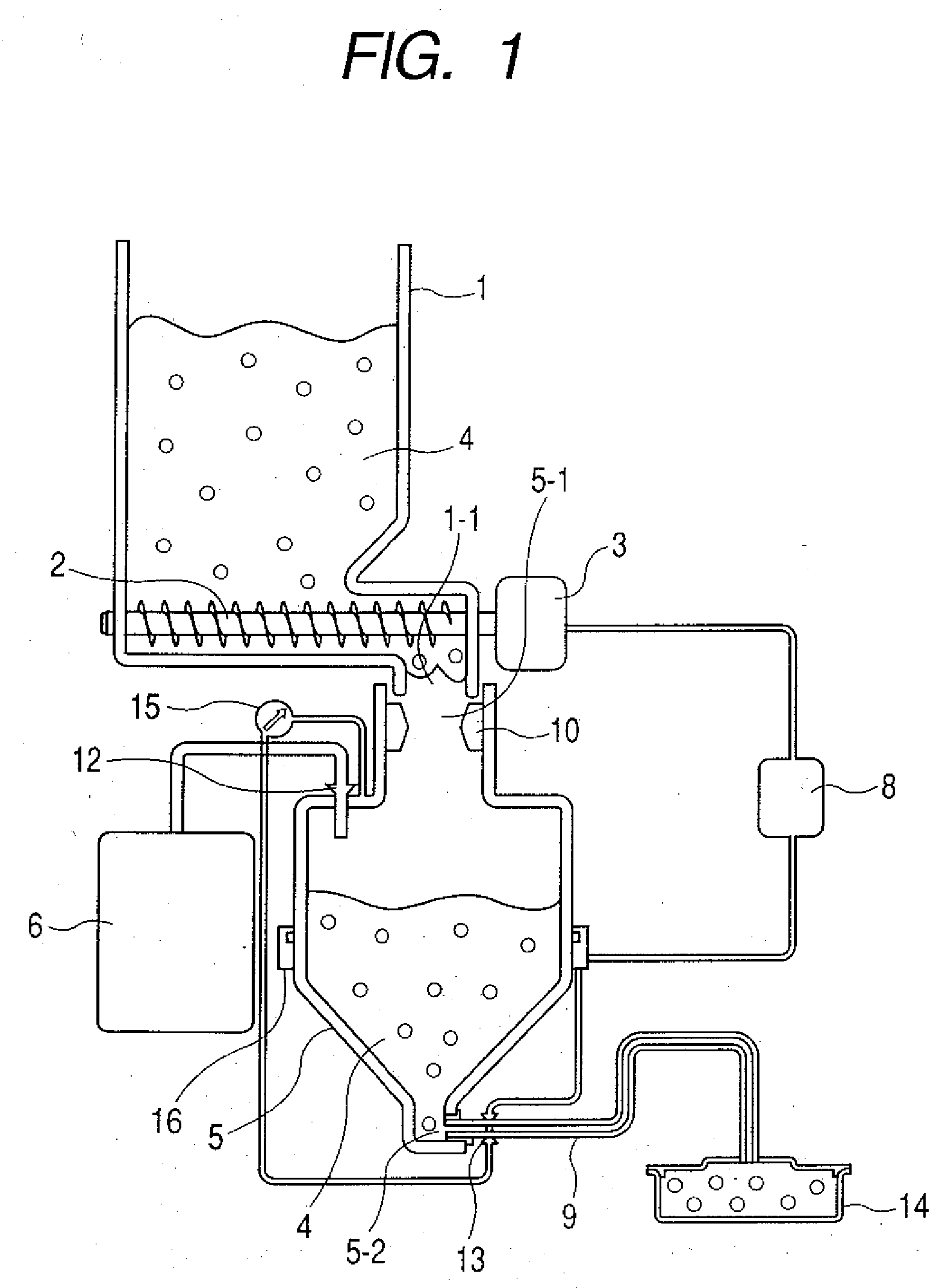
[0138]FIG. 1 shows an example of filling apparatus system using a filling apparatus according to the invention. Referring to FIG. 1, a powder reservoir 1 stores a large quantity of powder 4 to be filled. A carrying unit 2 for carrying a regular quantity of the powder 4 is disposed underneath the powder reservoir 1; the carrying unit 2 is driven by a driving unit 3 and carries the powder 4 stored in the reservoir 1 to a pressure hopper 5 disposed underneath.

[0139] The pressure hopper 5 is equipped with a compressor 6, a driving control device 8, a carrying tube 9, a powder intake valve 10, a pressurizing valve 12, a powder discharge valve 13, an internal pressure gauge 15 and a load cell 16.

[0140] Powder 4 carried from the reservoir 1 is led into the pressure hopper 5 through a powder inlet 5-1 of the pressure hopper 5 by opening the powder intake valve 10. When this takes place, the carrying tube 9 is cl...

embodiment 2

[0207] Next, a second exemplary embodiment of the invention will be described.

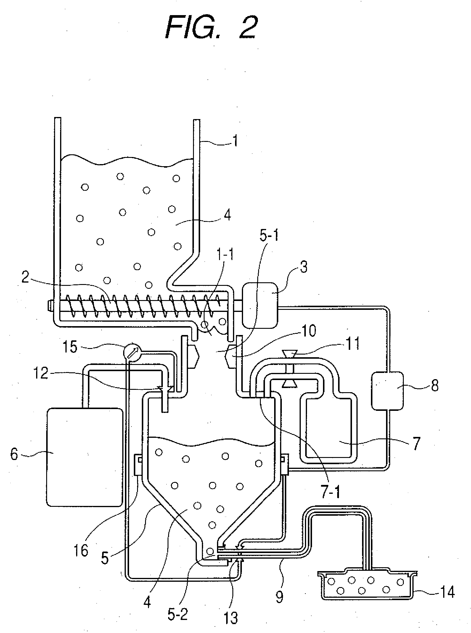
[0208]FIG. 2 shows an example of filling apparatus in a second exemplary embodiment of the invention. Referring to FIG. 2, the powder reservoir 1, pressure hopper 5, compressor 6, driving control device 8, carrying tube 9, powder intake valve 10, pressurizing valve 12, powder discharge valve 13, internal pressure gauge 15, load cell 16 and some other constituent elements are the same as their respective counterparts in Embodiment 1, and therefore their description will be dispensed with. The same kind of powder referred to in the description of Embodiment 1 can be used as powder 4.

[0209] A characteristic aspect of the filling apparatus, which is the second embodiment, lies in that an auxiliary container 7 and an auxiliary container valve 11 are linked to the pressure hopper 5.

[0210] The configuration of the auxiliary container 7 will be described with reference to FIG. 2.

[0211] As shown in FIG. 2, the ...

embodiment 3

[0221] Next, a third exemplary embodiment of the invention will be described.

[0222]FIG. 3 shows an example of filling apparatus in a third exemplary embodiment of the invention. Referring to FIG. 3, the powder reservoir 1, pressure hopper 5, compressor 6, driving control device 8, carrying tube 9, powder intake valve 10, pressurizing valve 12, powder discharge valve 13, internal pressure gauge 15, load cell 16 and some other constituent elements are the same as their respective counterparts in Embodiment 1, and therefore their description will be dispensed with. The same kind of powder referred to in the description of Embodiment 1 can be used as powder 4.

[0223] A characteristic aspect of the filling apparatus, which is the third embodiment, lies in that the rear end of the carriage path (the carrying tube 9) linked to the discharger which feeds powder into the filling container is formed of a deaerator 17 having a deaerating filter which has a shape that is substantially the same...


PUM

PropertyMeasurementUnit
pressureaaaaaaaaaa
timeaaaaaaaaaa
sizeaaaaaaaaaa

Abstract

A powder filling apparatus and a powder filling method which enable powder to be densely filled in a short period of time is to be provided. This is a powder filling apparatus having a pressure hopper wherein the pressure hopper has a discharger for discharging powder and a gas inlet positioned above at least the surface of a powder layer formed by the powder in the pressure hopper; the powder layer is so formed as to blockade the discharger in the pressure hopper; in the powder filling apparatus, the inside of the pressure hopper is pressurized by leading in gas through the gas inlet in a state in which the discharger is closed, and the powder layer so formed as to blockade the discharger is discharged by opening the discharger after the pressurization thereby to utilize that pressure to load the powder into the filling container.

Description

[0001] This application is a continuation of International Application No. PCT / JP2007 / 054361 filed on Feb. 28, 2007, which claims the benefit of Japanese Patent Application No. 2006-052216 filed on Feb. 28, 2006.BACKGROUND OF THE INVENTION [0002] 1. Field of the Invention [0003] The present invention relates to a powder filling apparatus and a powder filling method for packing fine powder such as toner used in the developing device of an imaging apparatus such as an electrostatic copying machine or a printer, into a filling container, and a process cartridge packed with the powder by the powder filling method. [0004] 2. Description of the Related Art [0005] Conventionally, fine powder such as toner is packed into a container to be filled with a powder with a screw feeder or an auger packer, by being let fall by its own gravity or by a pneumatic carrying device. For instance, Japanese Patent Application Laid-Open No. 2002-293301 describes an example of pneumatic method of carrying po...

Claims


Application Information

Patent Timeline
Patent Type & Authority Applications(United States)
IPC IPC(8): B65B1/16
CPCB65B1/16
Inventor ISOMURA, TETSUOJIMBA, MANABUKOSEKI, MASASHIJOMEN, KEIBAN, YUTAKA
Owner CANON KK
Learn More