

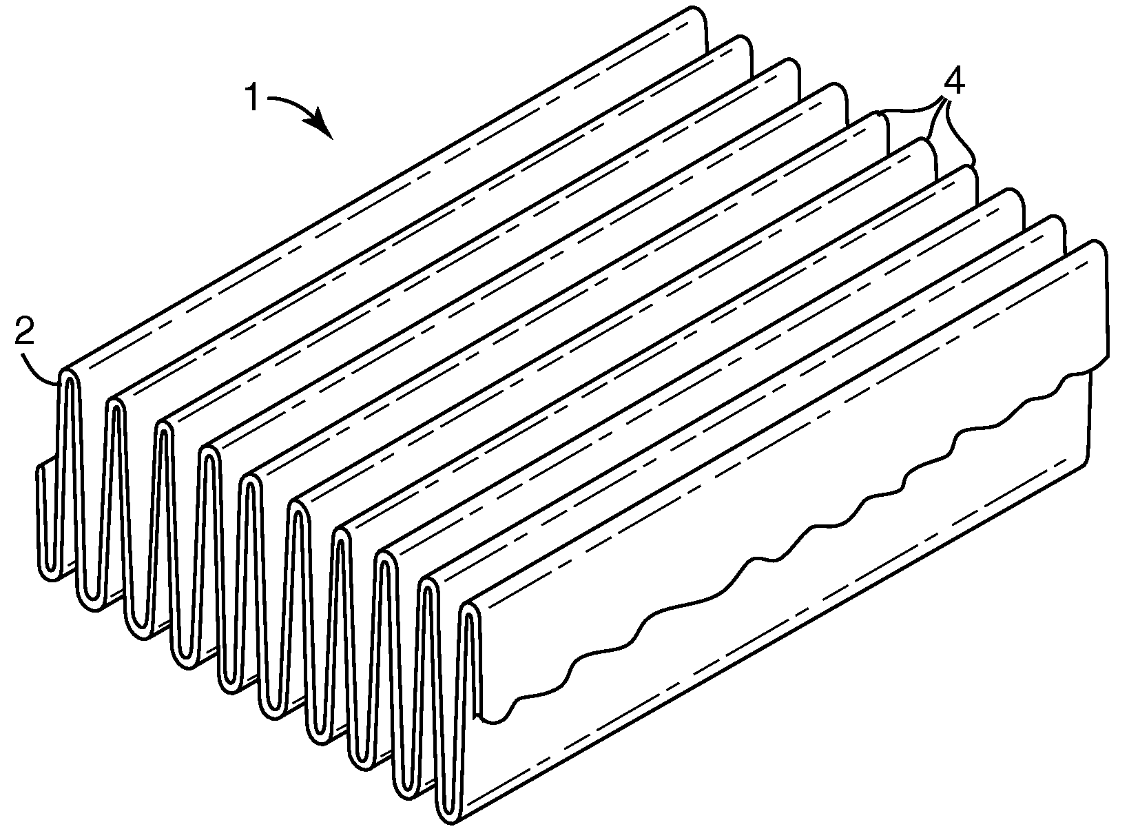
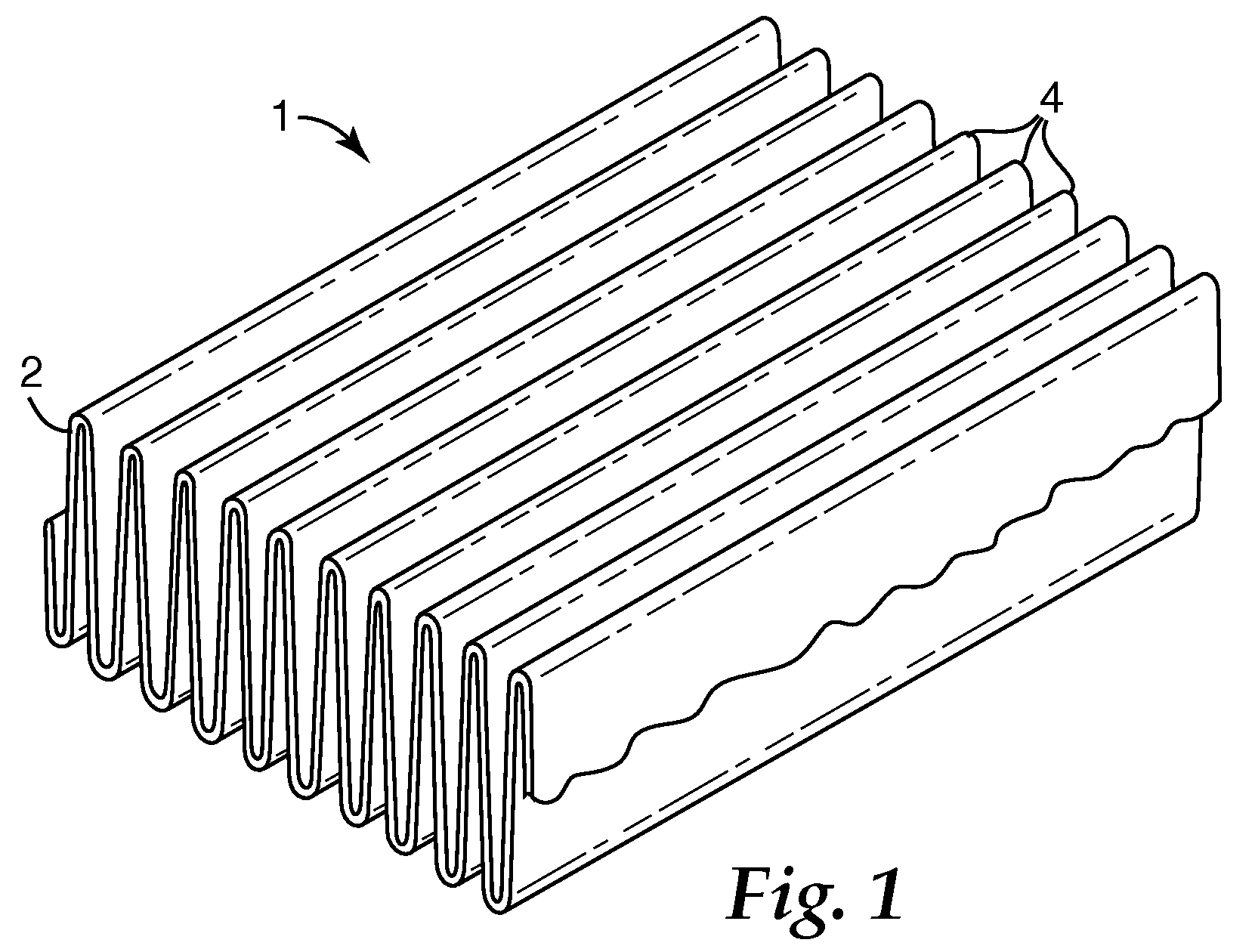
Pleated filter with monolayer monocomponent meltspun media
a technology of monocomponents and meltspun media, which is applied in the direction of bandages, separation processes, filtration separation, etc., can solve the problems of insufficient stiffness and strong to provide by itself a single layer filter media having high efficiency and adequate strength, and the manufacturing of a multilayer filter introduces additional cost and complexity to the filter product, so as to reduce product complexity and waste, improve formability, and reduce the effect of loss of filtration performan
- Summary
- Abstract
- Description
- Claims
- Application Information
AI Technical Summary
Benefits of technology
Problems solved by technology
Method used
Image

Examples
example 1
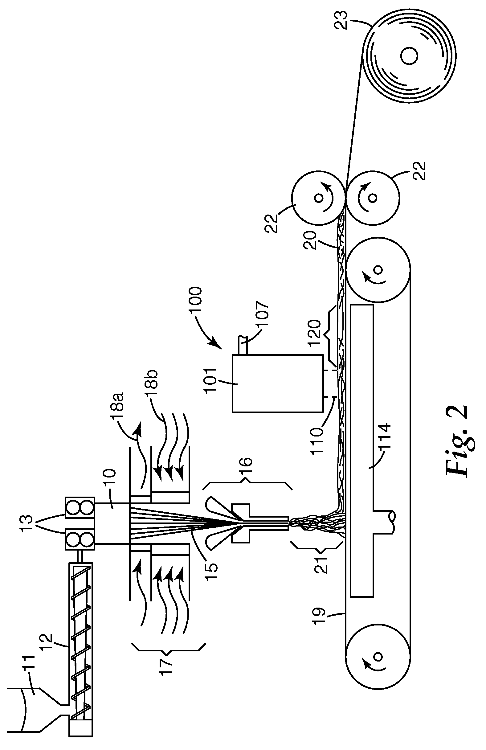
[0068]Using an apparatus like that shown in FIG. 2 through FIG. 4, a monocomponent monolayer web was formed from FINA™ 3868 polypropylene having a melt flow rate index of 37 available from Total Petrochemicals. The extrusion head 10 had 16 rows of orifices, with 32 orifices in a row, making a total of 512 orifices. The orifices were arranged in a square pattern (meaning that orifices were in alignment transversely as well as longitudinally, and equally spaced both transversely and longitudinally) with 0.25 inch (6.4 mm) spacing. The polymer was fed to the extrusion head at 0.6 g / hole / minute, where the polymer was heated to a temperature of 250° C. (482° F.). Two quenching air streams (18b in FIG. 2; stream 18a was not employed) were supplied as an upper stream from quench boxes 12 in. (305 mm) in height at an approximate face velocity of 5 ft / min (1.5 m / min) and a temperature of 45° F. (7.2° C.), and as a lower stream from quench boxes 12 in. (305 mm) in height at an approximate fac...
example 2
[0075]Using the general method of Example 1 except as otherwise indicated below, a monocomponent monolayer web was formed from FINA 3868 polypropylene. The extrusion head 10 had 18 rows of 36 orifices each, split into two blocks of 9 rows separated by a 0.63 in. (16 mm) gap in the middle of the die, making a total of 648 orifices. The orifices were arranged in a staggered pattern with 0.25 inch (6.4 mm) spacing. The polymer was fed to the extrusion head at 1.0 g / hole / minute. Two quenching air streams (18b in FIG. 2; stream 18a was not employed) were supplied as an upper stream from quench boxes 16 in. (406 mm) in height at an approximate face velocity of 83 ft / min (0.42 m / sec) and a temperature of 40° F. (4.4° C.), and as a lower stream from quench boxes 7.75 in. (197 mm) in height at an approximate face velocity of 28 ft / min (0.14 m / sec) and ambient room temperature. A movable-wall attenuator like that shown in Berrigan et al. was employed, using an air knife gap of 0.050 in. (1.27...
example 3
[0081]Using the general method of Example 2 except as otherwise indicated below, a monocomponent monolayer web was formed from FINA 3860 polypropylene having a melt flow rate index of 70 available from Total Petrochemicals, to which was added 0.75 wt. % of CHIMASSORB 944 hindered-amine light stabilizer from Ciba Specialty Chemicals. The polymer was fed to the extrusion head at 0.20 grams / hole / minute, where the polymer was heated to a temperature of 235° C. The upper quench air stream had a temperature of 45° F. (7.2° C.) and the lower quench air stream had an approximate face velocity of 31 ft / min (0.16 m / sec). A movable-wall attenuator like that shown in Berrigan et al. was employed, using an air knife gap of 0.030 in. (0.76 mm), air fed to the air knife at a pressure of 12 psig (0.08 MPa), and an attenuator top gap width of 0.20 in. (5.1 mm). The meltspun fiber stream was deposited on the collection belt 19 at a width of about 21 in. (about 53 cm). Collection belt 19 moved at a ra...
PUM
| Property | Measurement | Unit |
|---|---|---|
| Temperature | aaaaa | aaaaa |
| Fraction | aaaaa | aaaaa |
| Mass | aaaaa | aaaaa |
Abstract
Description
Claims
Application Information