Fluorescence conversion medium and color light-emitting device including the same
a technology of fluorescence conversion medium and color light, which is applied in the direction of material analysis using wave/particle radiation, instruments, optical means, etc., can solve the problems of lowering the fluorescent intensity of the fluorescence conversion medium with the lapse of time, the inability to obtain fluorescence quantum efficiency, and the inability to achieve fluorescence quantum efficiency, etc., to achieve a slight degree of deterioration and high fluorescence conversion efficiency
- Summary
- Abstract
- Description
- Claims
- Application Information
AI Technical Summary
Benefits of technology
Problems solved by technology
Method used
Image
Examples
example 1
(1) Production of Light Source Part
[0151] On a glass substrate with a dimension of 25 mm×75 mm×1.1 mm, ITO was applied to have a thickness of 130 nm by sputtering to obtain a transparent supporting substrate. Subsequently, the substrate was subjected to ultrasonic washing for 5 minutes in isopropyl alcohol. Then, the substrate was dried by blowing nitrogen, followed by 10-minute washing with UV ozone (UV 300, manufactured by Samco International Co., Ltd).
[0152] The transparent substrate was secured to a substrate holder of a commercially available vacuum deposition apparatus (manufactured by ULVAC, Inc). 200 mg of N,N′-bis(3-methylphenyl)-N,N′-diphenyl(1,1′-biphenyl)-4,4′-diamine (TPD) was put in a molybdenum resistant heating boat. 200 mg of 4,4′-bis (2,2′-diphenylvinyl)biphenyl (DPVBi) was put in another molybdenum resistant heating boat, and 200 mg of 4,4′-bis(2,4-N,N-diphenylaminophenylvinyl)biphenyl (DPAVBi) was put in still another molybdenum resistant boat. The pressure of...
example 2
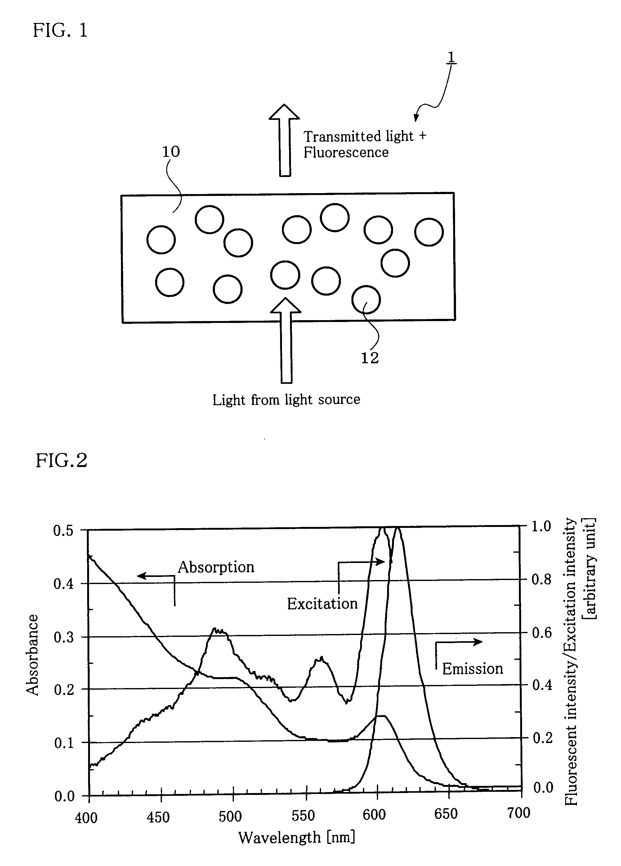
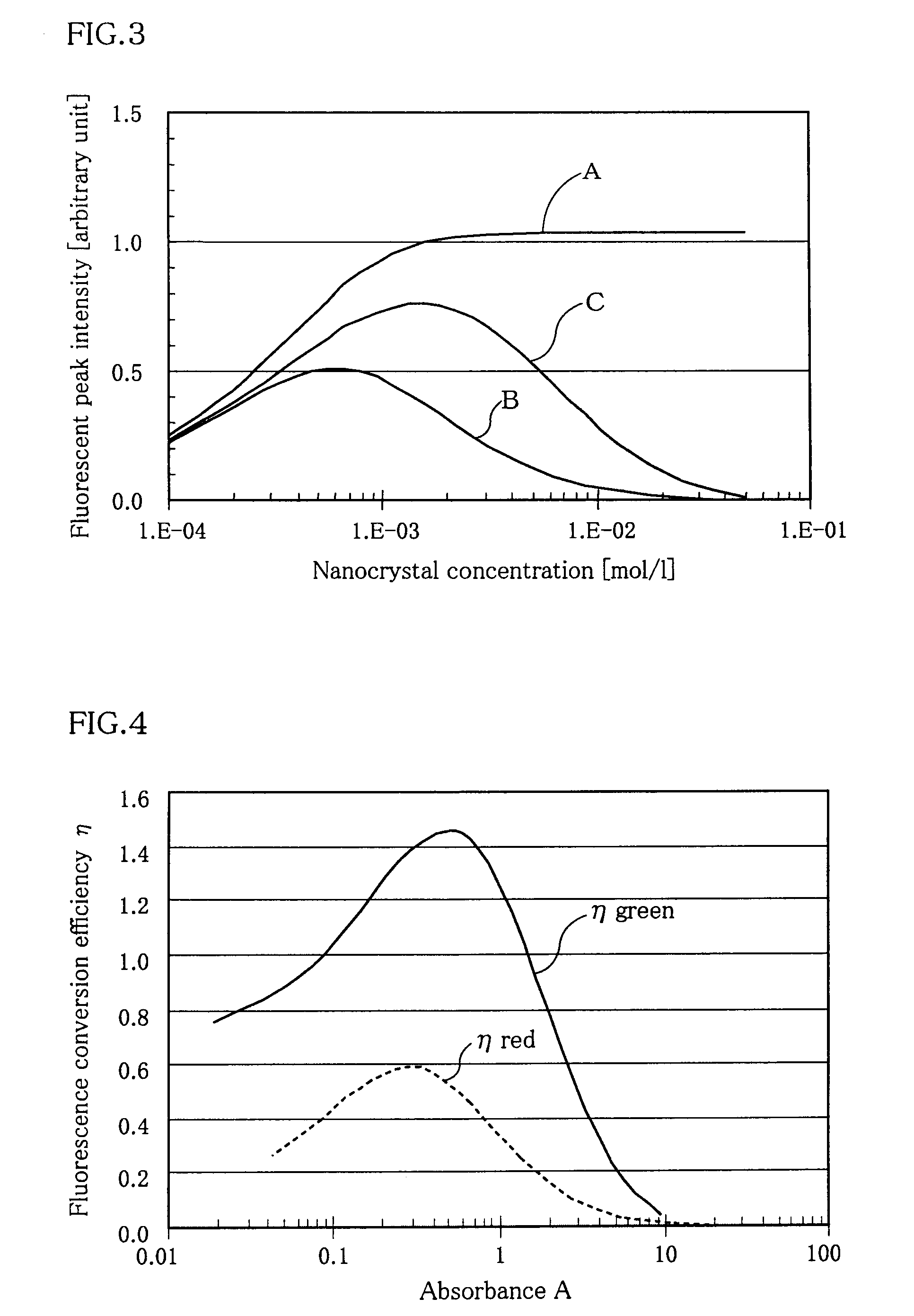
[0166] The same procedures as in Example 1 were followed, except that NC2 fine particles emitting green fluorescence were used instead of NC1 and the nanocrystal concentration of the film was changed to 8.5×10⁻³ mol / L and the film thickness was changed to 20 μm. The absorbance (A) of the fluorescence conversion medium at an emission peak wavelength (525 nm) was 0.81 and the value of overlapping (P) of emission and absorption was 23.6. As a result of the evaluation performed when combined with the light source part and the green color filter, it was found that the emission peak wavelength was 540 nm and the conversion efficiency reached 1.36. The CIE coordinate was (0.22, 0.72), which was satisfactory.
example 3
[0168] The same procedures as in Example 1 were followed, except that NC3 fine particles emitting red fluorescence were used instead of NC1 and the nanocrystal concentration of the film was changed to 7.0×10⁻⁴ mol / L and the film thickness was changed to 20 μm. The absorbance (A) of the fluorescence conversion medium at an emission peak wavelength (616 nm) was 0.19 and the value of overlapping (P) of emission and absorption of 5.3 were obtained. As a result of the evaluation performed when combined with the light source part and the red color filter, it was found that the emission peak wavelength was 622 nm and the conversion efficiency reached 0.55. The CIE coordinate was (0.66, 0.33), which was satisfactory.
PUM
 Abstract
Description
Claims
Application Information
 - R&D
- Intellectual Property
- Life Sciences
- Materials
- Tech Scout
- Unparalleled Data Quality
- Higher Quality Content
- 60% Fewer Hallucinations
Browse by: Latest US Patents, China's latest patents, Technical Efficacy Thesaurus, Application Domain, Technology Topic, Popular Technical Reports.
© 2025 PatSnap. All rights reserved.Legal|Privacy policy|Modern Slavery Act Transparency Statement|Sitemap|About US| Contact US: help@patsnap.com


