Low-microcracked, porous ceramic honeycombs and methods of manufacturing same

a technology of porous ceramics and honeycombs, applied in the field of porous honeycomb ceramics, can solve the problems of internal stress, microcracks throughout the body, and difficulty in meeting the requirements of strength and erosion resistance, and achieve the effect of low microcrack and high thermal shock

Active Publication Date: 2008-02-07
CORNING INC
View PDF24 Cites 57 Cited by
  • Summary
  • Abstract
  • Description
  • Claims
  • Application Information

AI Technical Summary

Benefits of technology

[0016] TSP≧525° C. wherein the thermal shock parameter (TSP) is defined as TSP=MORRT / [ERT][CTEH] (MORRT) is a room temperature modulus of rupture strength, and (CTEH) is high temperature thermal expansion coefficient between 500° C. and 900° C. MOR, E, and CTE are all measured on a cellular specimen parallel to the length of the channels, also referred to as the axial direction. EH is measured during heating from room temperature. Additionally, the invention may exhibit ERatio 1000≦1.01, ERatio 1000≦1.00, ERatio 1000≦0.98, ERatio 1000≦0.95, or even ERatio 1000≦0.93. Further, the honeycomb structures of the invention may exhibit relative low CTE, such as CTE (25-800° C.)≦18×10−7 / ° C., CTE (25-800° C.)≦16×10−7 / ° C., CTE (25-800° C.)≦15×10−7 / ° C., CTE (25-800° C.)≦14×10−7 / ° C., CTE (25-800° C.)≦12×10−7 / ° C., CTE (25-800° C.)≦10×10−7 / ° C., or even CTE (25-800° C.)≦9×10⁻⁷ / ° C. In addition to Eratio 1000≦1.05 and TSP≧525° C., as described above, further embodiments of the invention may be characterized by a pore microstructure of the porosity further including a relatively narrow pore size distribution. In particular, embodiments may additionally include a narrow pore size distribution wherein a porosity d-factor (df), defined by the equation df=(d50−d10) / d50, may be df≦0.48, df≦0.40, df≦0.37, df≦0.35, df≦0.30, df≦0.28, or even df≦0.25. Furthermore, the narrowness of the pore size distribution of the low microcracked honeycomb may be further defined by a pore microstructure wherein the overall pore size breadth (db), defined as db=(d90−d10) / d50, may be db≦1.65, db≦1.23, db≦1.21, db≦1.15, db≦1.00, db≦0.90, db≦0.80, or even db≦0.70. Lowering db increases filtration efficiency for filters, and strength for both filter and substrate applications.
[0017] Furthermore, the walls of the porous ceramic honeycombs of the invention may further include a preferred orientation wherein the cordierite crystallites in walls of the honeycomb structure have an preferred orientation exhibiting ΔI>0.1 wherein ΔI=IT−IA. In particular, the structure may include IA≦0.6, IA≦0.5, or even IA≦0.4. Additionally, for oriented examples, the structure may include IT≧0.7, or even IA≧0.8. The preferred orientation of the low-microcracked honeycomb reduces CTE in at least one direction. Furthermore, the cordierite structural honeycomb bodies of the present invention additionally may exhibit high pore connectivity, as defined by a Pore Connectivity Factor (PCF), defined by the relationship PCF=% P / (db), wherein PCF may be PCF≧40%, PCF≧45%, PCF≧50%, or even PCF≧55%. Moreover, PCF≧60%, PCF≧70%, PCF≧80% or even PCF≧90% have been demonstrated according to selected embodiments of the invention.
[0019] According to another aspect, the invention is a method for making a porous ceramic honeycomb structure, comprising the steps of mixing inorganic raw materials, an organic binder, and a liquid vehicle to form a plasticized batch, forming a green body from the plasticized batch, drying the green body, and firing the body to provide a cordierite ceramic structure having relatively low microcracking and relatively high thermal shock by exhibiting Eratio≦1.05 and TSP≧525° C.

Problems solved by technology

Further, the development of large (>50 μm) fan-like “domains” of radiating prismatic cordierite crystallites creates internal stresses during cooling that produce microcracks throughout the body.
For converters, the shift toward higher cell densities and thinner walls (e.g., 900 / 2) has created challenges in meeting requirements for strength and erosion resistance.
Microcracking may place a limit on the maximum strength achievable in the ceramic matrix itself.
A second problem arising from the use of converters and DPFs comprising microcracked cordierite may be the penetration of very fine catalyst washcoat particles into the microcracks formed in the cordierite matrix.
The presence of particles within the microcracks may interfere with closure of the microcracks during heating, essentially pinning the cracks open.
This may result in an increase in CTE, and also an increase in elastic modulus, both factors contributing to reduced thermal shock resistance.
This may be especially problematic for DPFs, where the catalyst washcoats are normally disposed within the porous walls of the filters.
Finally, the high degree of preferred “planar” orientation of cordierite required for low CTE can also present issues in cases where the degree of preferred orientation between the skin and the cellular matrix is different.
Consequently, during cooling from firing, the skin and matrix can contract at different rates, creating tensile stresses within the skin that may lead to the formation of cracks therein.
These cracks may reduce both strength and thermal shock resistance.
Based upon the above discussion, it is apparent that, while microcracking and preferred crystallite orientation have been essential in the past for achieving low CTE combined with high thermal shock resistance in reaction-sintered cordierite ceramics, both of these microstructural features can also create problems that may limit the utility of the material for certain applications.
Additionally, variable cordierite domain alignment can result in residual stresses in cordierite honeycombs.

Method used


Image

  • Low-microcracked, porous ceramic honeycombs and methods of manufacturing same
  • Low-microcracked, porous ceramic honeycombs and methods of manufacturing same
  • Low-microcracked, porous ceramic honeycombs and methods of manufacturing same

Examples


Embodiment Construction

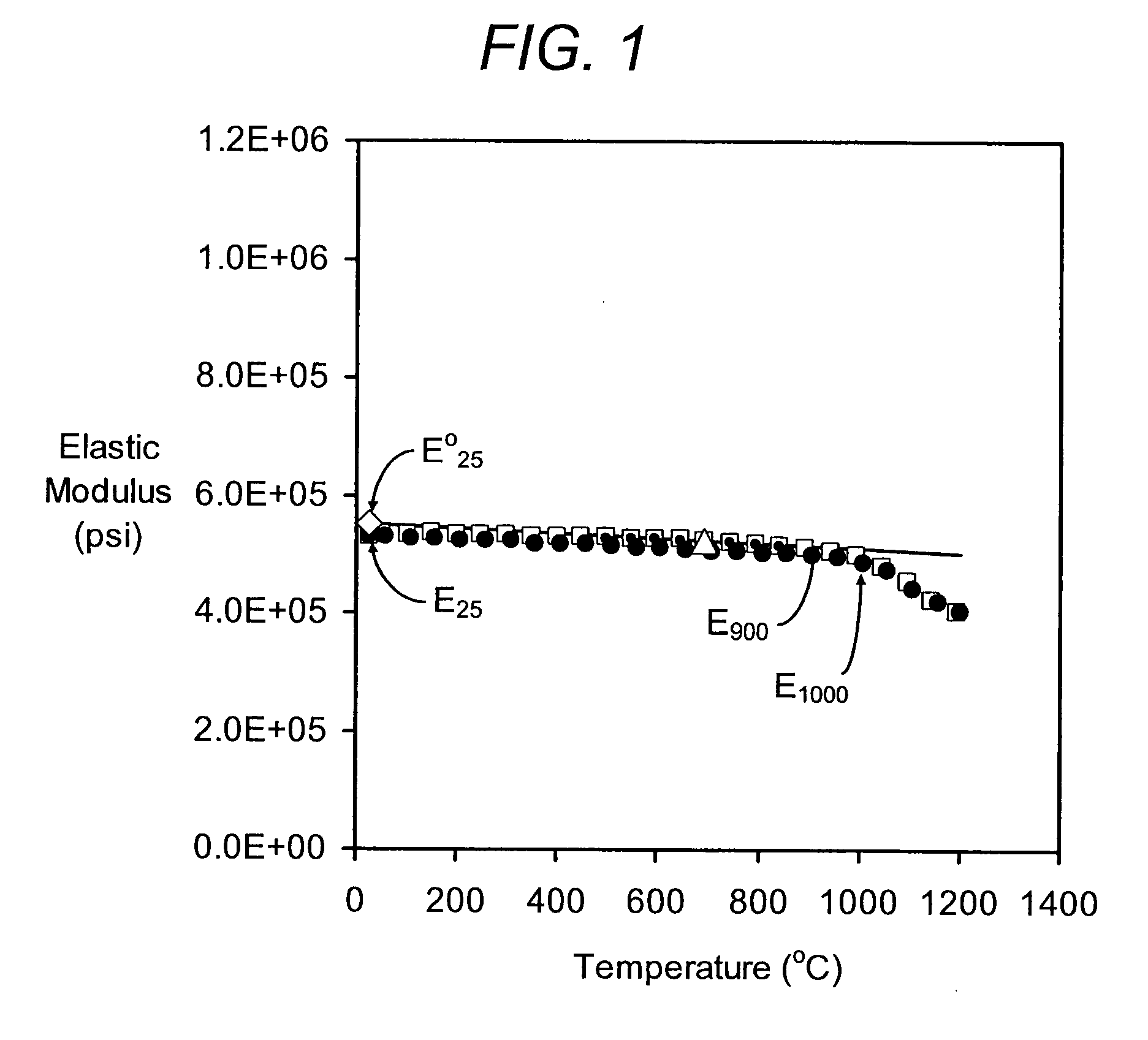
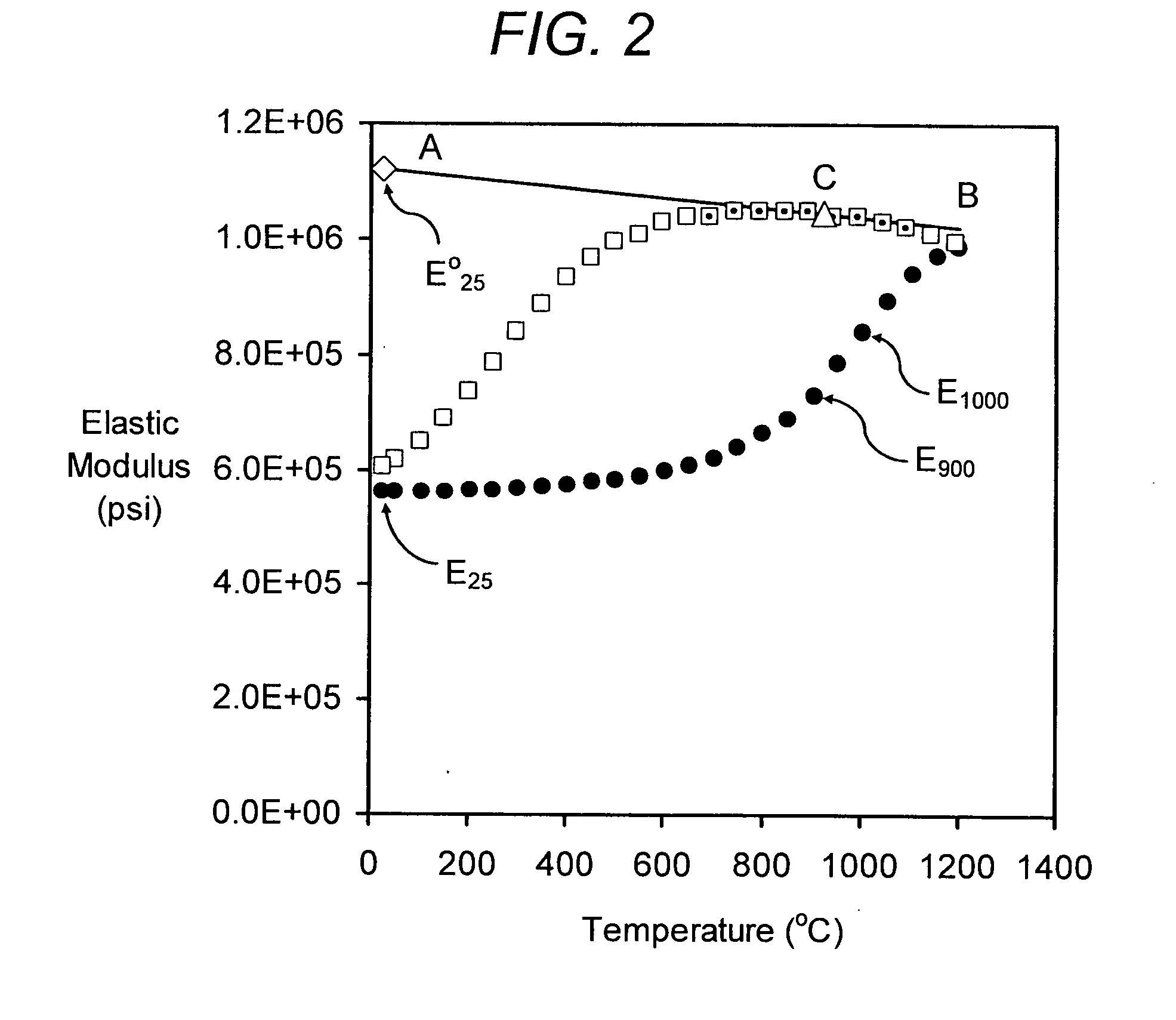
[0037] Securing a relatively low ratio of elastic modulus, Eratio 1000=EH 1000° C. / ERT in the cordierite ceramic honeycomb bodies of the invention is achieved by providing bodies formed of a substantially non-microcracked porous, cordierite ceramic material. Eratio 1000 values above 1.00 and below 1.05 are indicative of very minor, but tolerable, levels of microcracking (see FIG. 1), i.e., substantially non-microcracked bodies. Eratio 1000 values above 1.05 are indicative of relatively higher levels of microcracking (FIG. 2) which are less desirable in order to avoid adversely affecting product performance attributes, such as strength and insensitivity of thermal shock resistance to catalyzation. FIG. 1 is a plot of the elastic modulus (psi) versus temperature (° C.) during heating and cooling of an inventive low microcracked cordierite example of the invention (I41). Filled circles therein denote heating data, open squares denote cooling data, small filled circles within open squar...


PUM

PropertyMeasurementUnit
temperatureaaaaaaaaaa
domain sizeaaaaaaaaaa
porosityaaaaaaaaaa

Abstract

Substantially non-microcracked, porous, cordierite ceramic honeycomb bodies are provided. Although exhibiting moderately high thermal expansion (CTE) between 7×10⁻⁷ to 16×10−7 / ° C. (25-800° C.), the honeycomb bodies exhibit relatively high thermal shock parameter (TSP), such as TSR≧525° C. by virtue of a high MOR / E ratio, and / or low Eratio=ERT / E1000° C. and well interconnected porosity, as witnessed by a relatively high pore connectivity factor (PCF). A method of manufacturing the honeycomb ceramic structure is also provided.

Description

RELATED INVENTIONS [0001] This application claims priority to, and the benefit of, U.S. Provisional Application Ser. No. 60 / 840,806 filed Aug. 29, 2006 entitled “Non-Microcracked, Thermally Durable, Porous Ceramics,” U.S. Provisional Application Ser. No. 60 / 817,722 filed Jun. 30, 2006 entitled “High Porosity Filters for 4-Way Exhaust Gas Treatment,” and U.S. patent application Ser. No. 11 / 544,271 filed Oct. 6, 2006 and entitled “High Porosity Filters for 4-Way Exhaust Gas Treatment.”FIELD OF THE INVENTION [0002] The present invention is directed to porous honeycomb ceramics and methods of manufacturing same, and more particularly porous cordierite honeycomb ceramics useful in catalytic converters and particulate filters, such as for engine exhaust after-treatment. BACKGROUND OF THE INVENTION [0003] Porous ceramic honeycomb structures are widely used as catalytic converter substrates and / or diesel particulate filters. The earliest cordierite ceramic honeycombs for these applications ...

Claims


Application Information

Patent Timeline
Patent Type & Authority Applications(United States)
IPC IPC(8): B32B3/12
CPCC04B35/195Y10T428/24149C04B38/0009C04B2111/00793C04B2111/0081C04B2111/2084C04B2111/343C04B2111/346C04B2235/3206C04B2235/3217C04B2235/3218C04B2235/3222C04B2235/3418C04B2235/3445C04B2235/3463C04B2235/3472C04B2235/349C04B2235/36C04B2235/5436C04B2235/656C04B2235/6567C04B2235/80C04B2235/96C04B35/62665C04B38/0054C04B38/0074C04B38/067C04B38/068Y10T428/249953
Inventor BEALL, DOUGLAS MUNROEMELSCOET-CHAUVEL, ISABELLE MARIEMERKEL, GREGORY ALBERTTAO, TINGHONGTHOMPSON, DAVID JOHN
Owner CORNING INC
Why Eureka
Try Eureka