Compressed air cleaner utilizing a centrifugal impeller and spiral grooves

a technology of centrifugal impeller and compressed air, which is applied in the direction of machines/engines, mechanical equipment, separation processes, etc., to achieve the effects of saving energy, superior filtering efficiency, and small pressure loss

Inactive Publication Date: 2008-02-14
YUN JANG SHIK
View PDF23 Cites 23 Cited by
  • Summary
  • Abstract
  • Description
  • Claims
  • Application Information

AI Technical Summary

Benefits of technology

[0024] Compared to conventional technologies such as are represented in the foregoing citations and other prior arts, a compressed air cleaner utilizing a centrifugal impeller and spiral grooves according to the present invention is noted with the following advantages: no filter use, no clog problem with carbonated sludge, superior filtering efficiencies with small loss of pressure, energy saving, small, simple and compact structure, everlasting service term without periodic filter replacement, abatement of maintenance and repair fee on the various tools of pneumatic lines.
[0025] There are the improvements described with the followings a compressed air cleaner utilizing a centrifugal impeller and spiral grooves according to the present invention;
[0026] 1. Upgrading purification efficiency: it may be improved for compressed air purification efficiency without pressure loss and sludge clogging. Thus it may be prepared a liquid drain gap between the circumferential side of spiral grooves and the inner wall of housing on the basis of Labyrinth principle, since it is generated efficiently for the vortex flow of compressed air, further liquid is better separated with a centrifugal force from the vortex flow of compressed air and passed downwardly with a gravitational force to the liquid drain holes through a liquid drain gap between the circumferential side of spiral grooves and the inner wall of housing. Furthermore the vortex flow of compressed air may be not passed through a liquid drain gap between the circumferential side of spiral grooves and the inner wall of housing on the basis of Labyrinth principle. Therefore a liquid drain gap is formed between the circumferential side of spiral grooves 216 and inner wall of a housing 209, a spiral air passage is formed between the circumferential side of spiral grooves 216 and inner wall of a housing 209 on the basis of labyrinth principle.
[0027] 2. Horizontal piping: It may be usually installed for a compressed air cleaner on a horizontal pipe in industrial facility. Thus it is improved for arranging an inlet nipple and an outlet nipple horizontally on the structure of a housing. Therefore an inlet air passage 231 and an inlet air passage 232 are formed horizontally with same level on the circumferential surface of a housing 209.
[0028] 3. A shaft fixed with both ends: It may be lack of the durability on the structure of a one arm shaft fixed with one end, Thus it may be improved for a mechanical life with a shaft fixed with both ends.
[0029] 4. Low mass cast-manufacturing cost: It may be improved for simplifying with low manufacturing cost and easy maintenances.

Problems solved by technology

Vertical piping, it is inconvenient for installing a compressed air cleaner on a pipe in industry, since a compressed air cleaner may be usually installed with a horizontal pipe in industrial facility Thus it is improved for arranging an inlet nipple and an outlet nipple horizontally on the structure of a housing.

Method used


Image

  • Compressed air cleaner utilizing a centrifugal impeller and spiral grooves
  • Compressed air cleaner utilizing a centrifugal impeller and spiral grooves
  • Compressed air cleaner utilizing a centrifugal impeller and spiral grooves

Examples


Embodiment Construction

[0046] The Invention Preferred embodiments of the present invention will be explained hereafter with reference to accompanied embodiments.

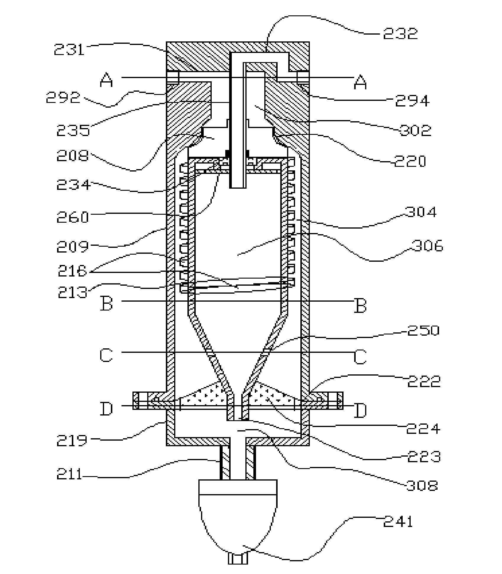
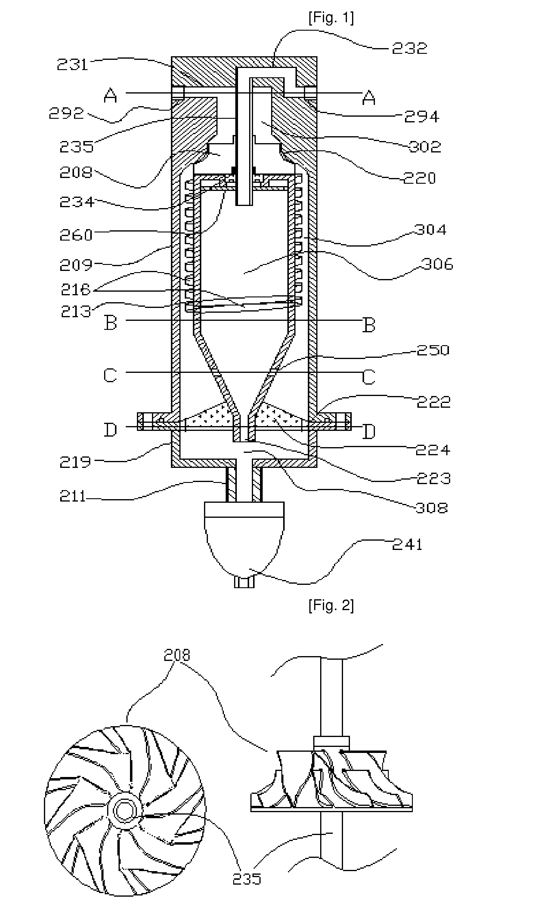
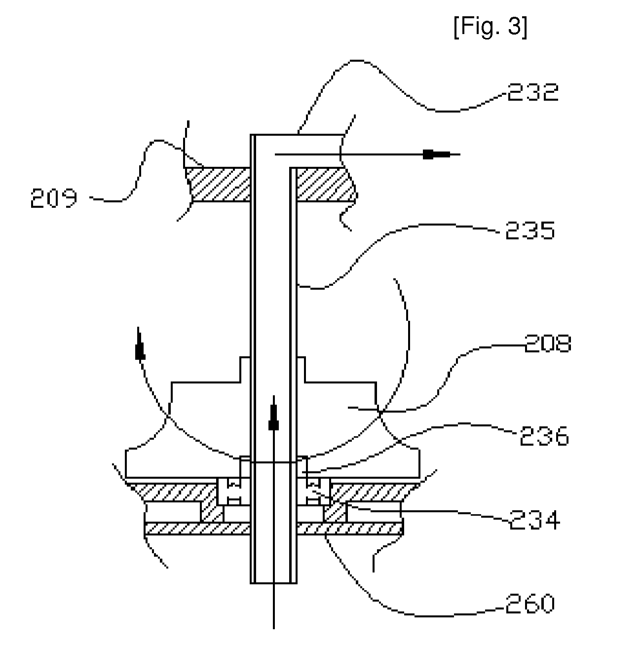
[0047] As shown in FIG. 1, a compressed air cleaner utilizing a centrifugal impeller and spiral grooves by operating with the jet power of compressed air, comprising: a vortex cylinder 213 located inside of a housing 209, a separating plate 260 located on the upper side of a vortex cylinder 213, spiral grooves 216 formed on the circumferential surface of a vortex cylinder 213 for separating liquid from compressed air with centrifugal force after forming vortex flow and draining liquid in keeping with the vortex flow of compressed air on the basis of labyrinth principle, and a hallow shaft 235 formed a compressed air passage on its axis and fixed on its both ends between a housing 209 and a vortex cylinder 213, a centrifugal impeller 208 and a bearing 234 installed on a hollow shaft 235, and multiple air passages 250 formed on the circumferential ...


PUM

PropertyMeasurementUnit
centrifugal force lengthaaaaaaaaaa
purityaaaaaaaaaa
flow ratesaaaaaaaaaa

Abstract

This invention relates to a compressed gas cleaner utilizing a centrifugal impeller and spiral grooves by spinning a centrifugal impeller automatically with the dynamic power of compressed gas from a compressor, thus the separation of liquid, water, oil sludge and particular pollution dust can be completely cleaned with the spiral grooves instead of solid filters on the basis of specific difference, 1 to 1000, between gas and liquid. A compressed gas cleaner utilizing a centrifugal impeller and spiral grooves comprising: the spiral grooves for generating centrifugal gas stream without loss of pressure and the path of a liquid flow without sludge plugging on the basis of the labyrinth principle. Thus it is upgraded for a higher gas cleaning efficiency, 99.9% without any kind of solid filtering elements, drying chemicals and dehumidifying refrigerators on the basis of simple parts and structure for horizontal piping, low manufacturing fee, easy assembly and free maintenance for many years.

Description

TECHNICAL FIELD [0001] This invention relates to a compressed air cleaner utilizing a centrifugal impeller and spiral grooves, thus the separation of dirty liquid including water, oil and particular pollution dust can be carried out with the centrifugal power efficiently from compressed air. [0002] Compressed air generation uses an expensive cost of input energy, however compressed air includes lot of water, coolant oil, carbonated material and rusted pollution contaminants. Thus compressed air typically must be dry and purify for the usual applications. Besides the need for clean ambient air, it should be stressed that the quality of compressed air is important. [0003] The need for high standards of compressed air purity for many uses is obvious, particularly for electronic industry, automobile industry, food processing, pharmaceutical manufacturing, hospital tools and other highly precession controlled operations. [0004] In numerous situations, a continuous liquid or gas phase is ...

Claims


Application Information

Patent Timeline
Patent Type & Authority Applications(United States)
IPC IPC(8): B01D45/00B01D45/14F01N3/00F01N3/037
CPCF01N3/005B01D45/14F01N3/037
Inventor YUN, JANG-SHIK
Owner YUN JANG SHIK
Why Eureka
Try Eureka