AT cut quartz crystal resonator element and method for manufacturing the same

a quartz crystal and resonator technology, applied in piezoelectric/electrostrictive transducers, generators/motors, device material selection, etc., can solve the problem of insufficient energy tapping effect in the z′-axis direction, difficult to improve frequency characteristics such as ci value or q value, and the possibility of damaging the quartz crystal substrate itself. problem, to achieve the effect of eliminating an effect, improving frequency characteristics such as ci value or q value, and width-shear mod

Active Publication Date: 2008-02-14
SEIKO EPSON CORP
View PDF3 Cites 19 Cited by
  • Summary
  • Abstract
  • Description
  • Claims
  • Application Information

AI Technical Summary

Benefits of technology

[0018]Furthermore, another advantage of the invention is to effectively eliminate an effect of an unnecessary wave which has a possibility of superposing on a main vibration, in the case of the AT cut quartz crystal resonator element in a mesa shape having a thick center potion and a thin surrounding portion.
[0019]According to an aspect of the invention, an AT cut quartz crystal resonator element includes a quartz crystal element piece having an exciting part formed from an AT cut quartz crystal plate in a rectangular shape having an X-axis direction of a quartz crystal set to a long side, and an exciting electrode formed on each of front and back main surfaces of the exciting part, in which each of both side surfaces in the longitudinal direction of the exciting part is composed of two faces, an m-face of a quartz crystal and a crystal face other than the m-face.
[0020]It has turned out that the AT cut quartz crystal resonator element, which has the side surfaces in the longitudinal direction each composed of two surfaces tilted at different angles with respect to the front and back main surfaces of the exciting part, i.e., the AT cut surface, is greatly improved in terms of a vibration energy trapping effect at both ends in a width direction. Therefore, frequency characteristics such as CI value or Q value can be improved without processing the main surface of the resonator element in a convex shape. Furthermore, since each side surface in the longitudinal direction of the resonator element is partially composed of the crystal face of the quartz making an angle of about 3 degrees with respect to a normal direction of the main surface...

Problems solved by technology

However, the aforementioned AT cut quartz crystal resonator according to JP-A-2005-94410 has a problem that an energy tapping effect cannot be obtained sufficiently in the Z′-axis direction, i.e., a width direction of the resonator element. FIG. 8C shows vibration displacement in the width direction of the AT cut quartz crystal resonator element 10 shown in FIG. 8B.
Therefore, it becomes difficult to improve the frequency characteristics such as the CI value or the Q value.
Furthermore, a longer etching time than normal is required to perform the overetching to the quartz crystal substrate, leading to possibility of damaging the quartz crystal substrate itself.
As described above, the piezoelectric resonator element in the convex shape achieves the high energy trapping effect but has a problem that it is difficult to process the outline into a desired shape.
For example, it is difficult by the mechanical process using the barrel polishing, to control the processing accuracy, resulting in a wide range of variation in a shape and a size.
Furthermore, this mechanical process requires the long processing time, leading to ...

Method used


Image

  • AT cut quartz crystal resonator element and method for manufacturing the same
  • AT cut quartz crystal resonator element and method for manufacturing the same
  • AT cut quartz crystal resonator element and method for manufacturing the same

Examples


Embodiment Construction

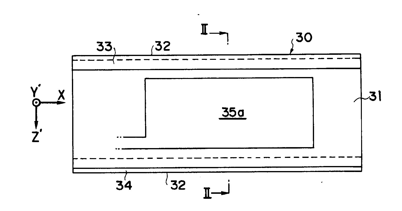
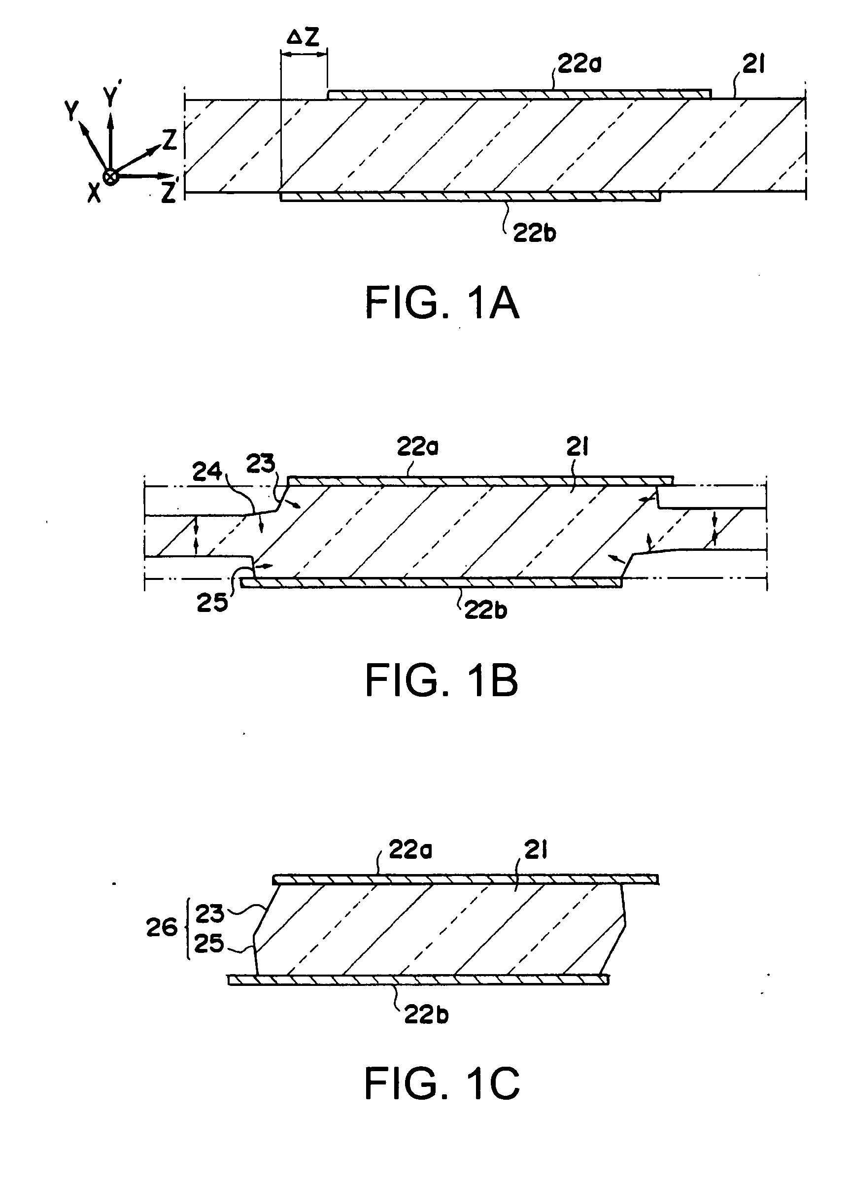
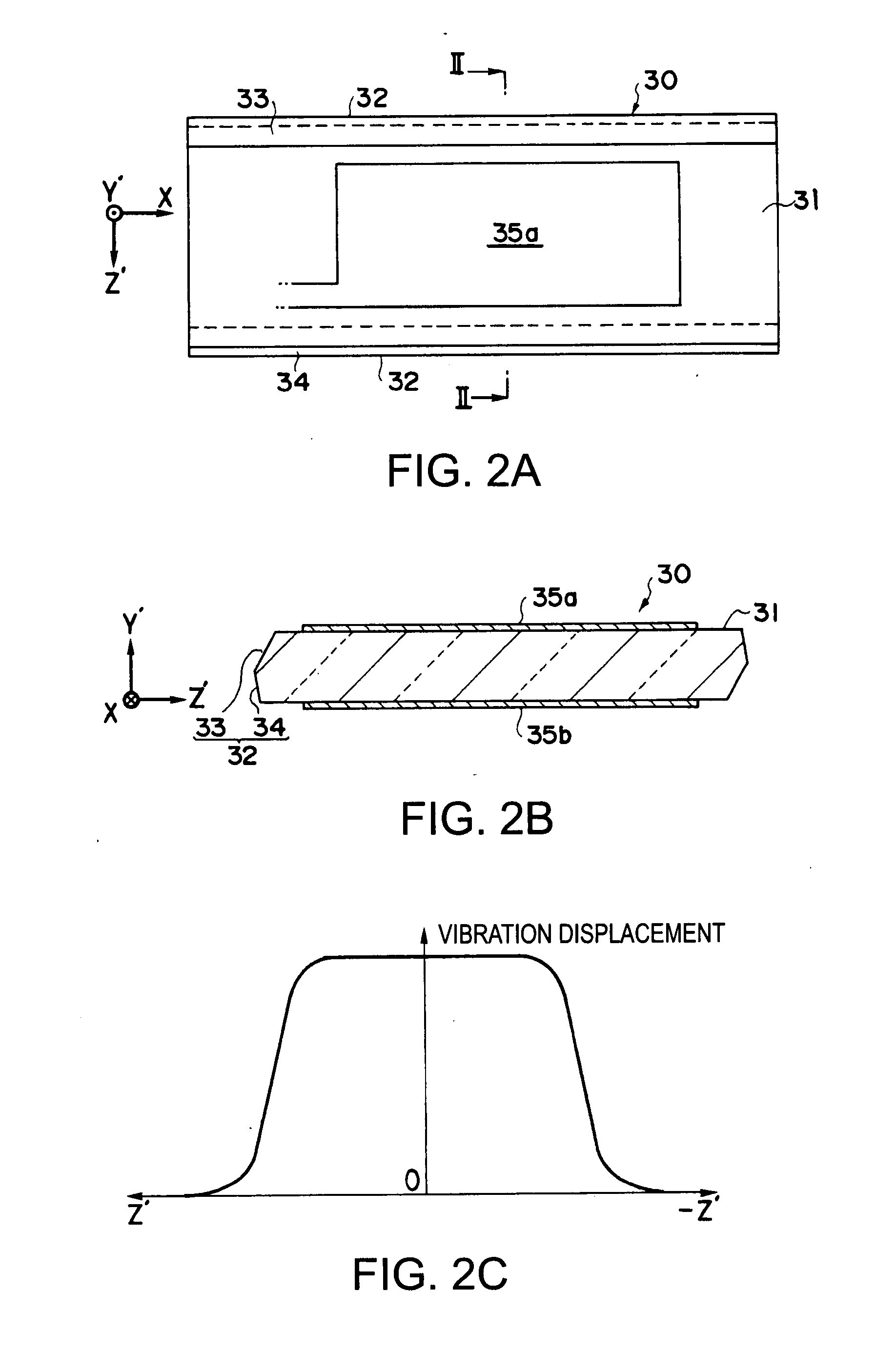
[0047]Hereinafter, preferred embodiments according to this invention will be explained with reference to accompanying drawings. FIGS. 1A through 1C show in order of procedural steps a process of processing an outline of an AT cut quartz crystal element by a method according to this invention. In this embodiment, right-handed quartz is used as shown in drawings, and an outline of a quartz crystal element piece is processed in a manner that an X-axis direction of the quartz is set to a long side and a Z′-axis direction is set to a thickness. First, an AT cut quartz crystal is subjected to a lapping process or the like to prepare an AT cut quartz crystal substrate 21 having a desired flat surface and thickness. First, masks 22a, 22b are formed on both upper and lower main surfaces of the quartz crystal substrate 21 by performing vapor deposition of a Cr film and an Au film each having a predetermined thickness and then photo-etching, as shown in FIG. 1A. At this time, the mask 22a at a...


PUM

PropertyMeasurementUnit
Fractionaaaaaaaaaa
Angleaaaaaaaaaa
Thicknessaaaaaaaaaa

Abstract

An AT cut quartz crystal resonator element includes a quartz crystal element piece having an exciting part formed from an AT cut quartz crystal plate in a rectangular shape having an X-axis direction of a quartz crystal set to a long side, and an exciting electrode formed on each of front and back main surfaces of the exciting part, in which each side surface in the longitudinal direction of the exciting part is composed of two faces, an m-face of a quartz crystal and a crystal face other than the m-face.

Description

BACKGROUND OF THE INVENTION[0001]1. Technical Field[0002]The present invention relates to an AT cut quartz crystal resonator element having a thickness-shear vibration mode as a main vibration and a method for manufacturing the same.[0003]2. Related Art[0004]Generally, a quartz crystal that achieves a high frequency while having stable frequency characteristics is widely adopted as a piezoelectric material for a piezoelectric device such as a resonator, an oscillator, a filter, or a sensor. Especially an AT cut quartz crystal plate is the most widely used material for a quartz crystal resonator having a thickness-shear vibration mode as a main vibration because of the characteristics that a frequency change is small compared with a temperature change around room temperature. The AT cut quartz crystal plate is cut from a quartz crystal, in which a main surface is set by rotating a surface containing an X-axis and a Z-axis around the X-axis counterclockwise from the Z-axis by an angle...

Claims


Application Information

Patent Timeline
IPC IPC(8): H03H9/19H03H3/02H01L41/09H01L41/18H01L41/22H01L41/332H01L41/39
CPCH03H3/04H03H9/02007H03H9/02102Y10T29/42H03H9/177H03H9/19H03H9/0595H03H3/02
Inventor NAITO, MATSUTAROAOSHIMA, YOSHIYUKIKOMINE, KENJI
Owner SEIKO EPSON CORP
Why Eureka
Try Eureka